
Power impact tool

a tool and power technology, applied in the direction of power driven tools, wrenches, screwdrivers, etc., can solve the problems of large difference between the actual torque and the desired torque of the fastening member, damage to the usability, and increased cost, and achieve the effect of low cost power

Active Publication Date: 2005-09-20
MATSUSHITA ELECTRIC WORKS LTD
View PDF13 Cites 78 Cited by
  • Summary
  • Abstract
  • Description
  • Claims
  • Application Information

AI Technical Summary

Benefits of technology

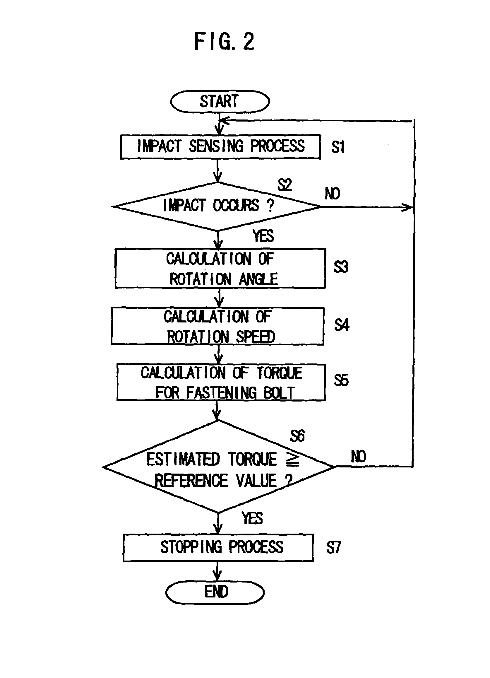
"The present invention provides a low cost power impact tool for fastening a fastening member. The tool uses sensors to estimate the torque for fastening without the need for high-resolution sensors and high-speed processors. The tool includes a hammer, a driving mechanism, an output shaft, an impact sensor, a rotation speed sensor, a rotation angle sensor, a torque estimator, a torque setter, and a controller. The torque estimator calculates the impact energy by averaging the rotation speed between the impacts of the hammer and divides it by the rotation angle of the output shaft to estimate the torque for fastening. The tool can be used with an inexpensive microprocessor."

Problems solved by technology

The first conventional power impact tool which stops the driving of the motor corresponding to the actual torque for fastening the fastening member needs a sensor provided on an output shaft for sensing the actual torque, so that it causes the cost increase and the damage of the usability owing to the upsizing of the power impact tool, even though the automatic stopping of the driving of the motor can be controlled precisely corresponding to the actual torque.
The second conventional power impact tool, however, has a disadvantage that a large difference may occur between a desired torque and the actual torque for fastening the fastening member, even though the control for stopping the motor can easily be carried out.
The difference causes loosening of the fastening member due to insufficient torque when the actual torque is much smaller than the desired torque.
Alternatively, the difference causes to damage the component to be fastened by the fastening member or to damage a head of the fastening member due to superfluous torque when the actual torque is much larger than the desired torque.
The power impact tool using a battery as a power source, however, has a disadvantage that the torque for fastening the fastening member largely varies due to the drop of voltage of the battery.
Furthermore, the torque for fastening the fastening member is largely affected by the hardening of a material of a component to be fastened by the fastening member.
Since the fourth conventional power impact tool senses the impact energy based on an instantaneous speed at the impact occurs, it needs a high-resolution sensor and a high-speed processor, which is the cause of expensiveness.

Method used


Image

  • Power impact tool
  • Power impact tool
  • Power impact tool

Examples


Embodiment Construction

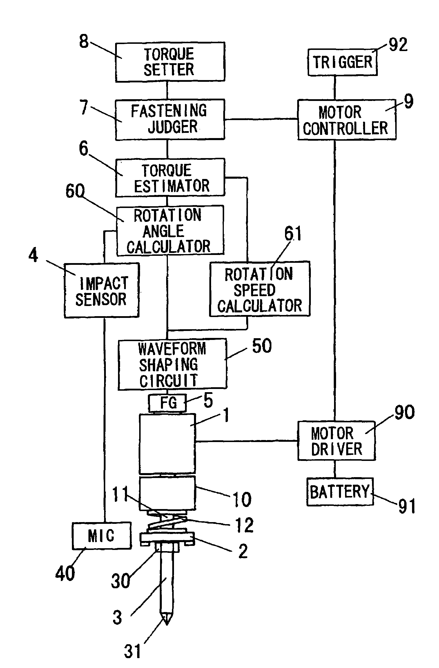
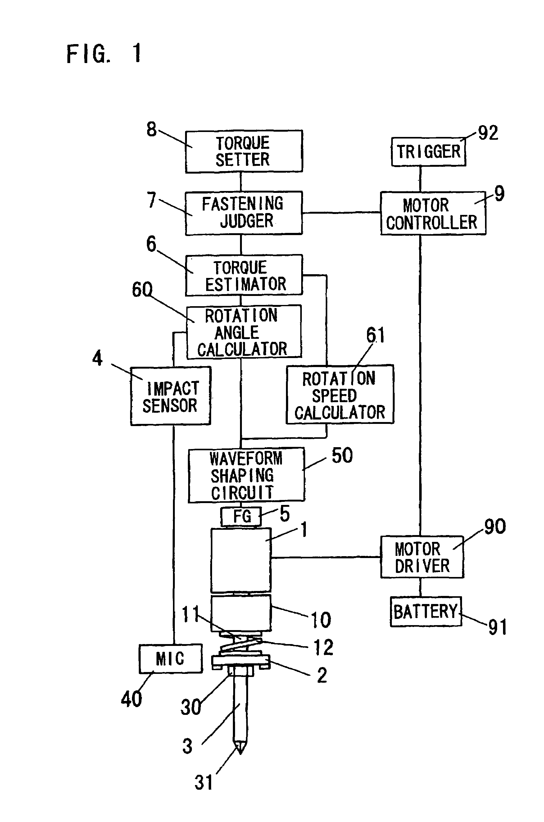
[0033]A power impact tool in accordance with an embodiment of the present invention is described. FIG. 1 shows a configuration of the power impact tool in this embodiment.

[0034]The power impact tool comprises a motor 1 for generating a driving force, a reducer 10 having a predetermined reduction ratio and for transmitting the driving force of the motor 1 to a driving shaft 11, a hammer 2 engaged with the driving shaft 11 via a spline bearing, an anvil 30 engaged with the driving shaft 11 with a clutch mechanism, and a spring 12 for applying pressing force to the hammer 2 toward the anvil 30. The motol 1, the reducer 10, the driving shaft 11, and so on constitute a driving mechanism.

[0035]The hammer 2 can be moved in an axial direction of the driving shaft 11 via the spline bearing, and rotated with the driving shaft 11. The clutch mechanism is provided between the hammer 2 and the anvil 30. The hammer 2 is pressed to the anvil 30 by the pressing force of the spring 12 in an initial ...


PUM


Abstract

In a power impact tool for fastening a fastening member, a torque for fastening the fastening member can be estimated without using a high-resolution sensor and a high-speed processor. The power impact tool comprises a rotation speed sensor for sensing a rotation speed of a driving shaft of a motor with using a rotation angle of the driving shaft, a rotation angle sensor for sensing a rotation angle of an output shaft to which a bit is fitted in a term between an impact of a hammer to next impact of the hammer, a torque estimator for calculating an impact energy with using an average rotation speed of the driving shaft and for calculating a value of estimated torque for fastening the fastening member which is given as a division of the impact energy by the rotation angle of the output shaft, a torque setter for setting a reference value of torque to be compared, and a controller for stopping the driving of the motor when the value of the estimated torque becomes equal to or larger than a predetermined reference value set by the torque setter.

Description

BACKGROUND OF THE INVENTION[0001]1. Field of the Invention[0002]The present invention relates to a power impact tool such as an impact driver or an impact wrench used for fastening a fastening member such as a bolt or a nut.[0003]2. Description of the Related Art[0004]In a power impact tool used for fastening a fastening member such as a bolt or a nut, it is preferable that a fastening operation is automatically completed by stopping the driving of a driving source such as a motor, when a torque for fastening the fastening member reaches to a predetermined reference value previously set.[0005]In a first conventional power impact tool shown in publication gazette of Japanese Patent Application 6-91551, an actual torque, which is necessary for fastening the fastening member, is sensed and the driving of a motor is stopped when the actual torque reaches to a predetermined reference value. The first conventional power impact tool which stops the driving of the motor corresponding to the...

Claims


Application Information

Patent Timeline
Patent Type & Authority Patents(United States)
IPC IPC(8): B25B21/02B25B23/14B25B21/00
CPCB25B21/026B25B23/1405
Inventor KAWAI, KOZOSAINOMOTO, YOSHINORIMATSUMOTO, TATSUHIKOARIMURA, TADASHIOHASHI, TOSHIHARUMIYAZAKI, HIROSHISHIMIZU, HIDENORISAWANO, FUMIAKI
Owner MATSUSHITA ELECTRIC WORKS LTD
Learn More