Rail inspection system

rail technology, applied in the direction of instruments, specific gravity measurement, fluid analysis using sonic/ultrasonic/infrasonic waves, etc., can solve the problems of not describing a rail inspection system that allows bidirectional evaluation and detection of rail tracks, and achieves low manufacturing cost, easy and efficient manufacturing and marketing, and durable and reliable construction

Inactive Publication Date: 2008-06-24
WAVESINSOLIDS
View PDF9 Cites 46 Cited by
  • Summary
  • Abstract
  • Description
  • Claims
  • Application Information

AI Technical Summary

Benefits of technology

[0020]It is another object of the present invention to provide a new and improved rail inspection system which may be easily and efficiently manufactured and marketed.
[0021]It is further object of the present invention to provide a new and improved rail inspection system which is of durable and reliable constructions.
[0022]An even further object of the present invention is to provide a new and improved rail inspection system which is susceptible of a low cost of manufacture with regard to both materials and labor, and which accordingly is then susceptible of low prices of sale to the consuming public, thereby making such rail inspection system economically available.

Problems solved by technology

While these devices fulfill their respective, particular objectives and requirements, the aforementioned patents do not describe a rail inspection system that allows bidirectionally evaluating and detecting flaws in railroad tracks.

Method used


Image

  • Rail inspection system
  • Rail inspection system
  • Rail inspection system

Examples


Embodiment Construction

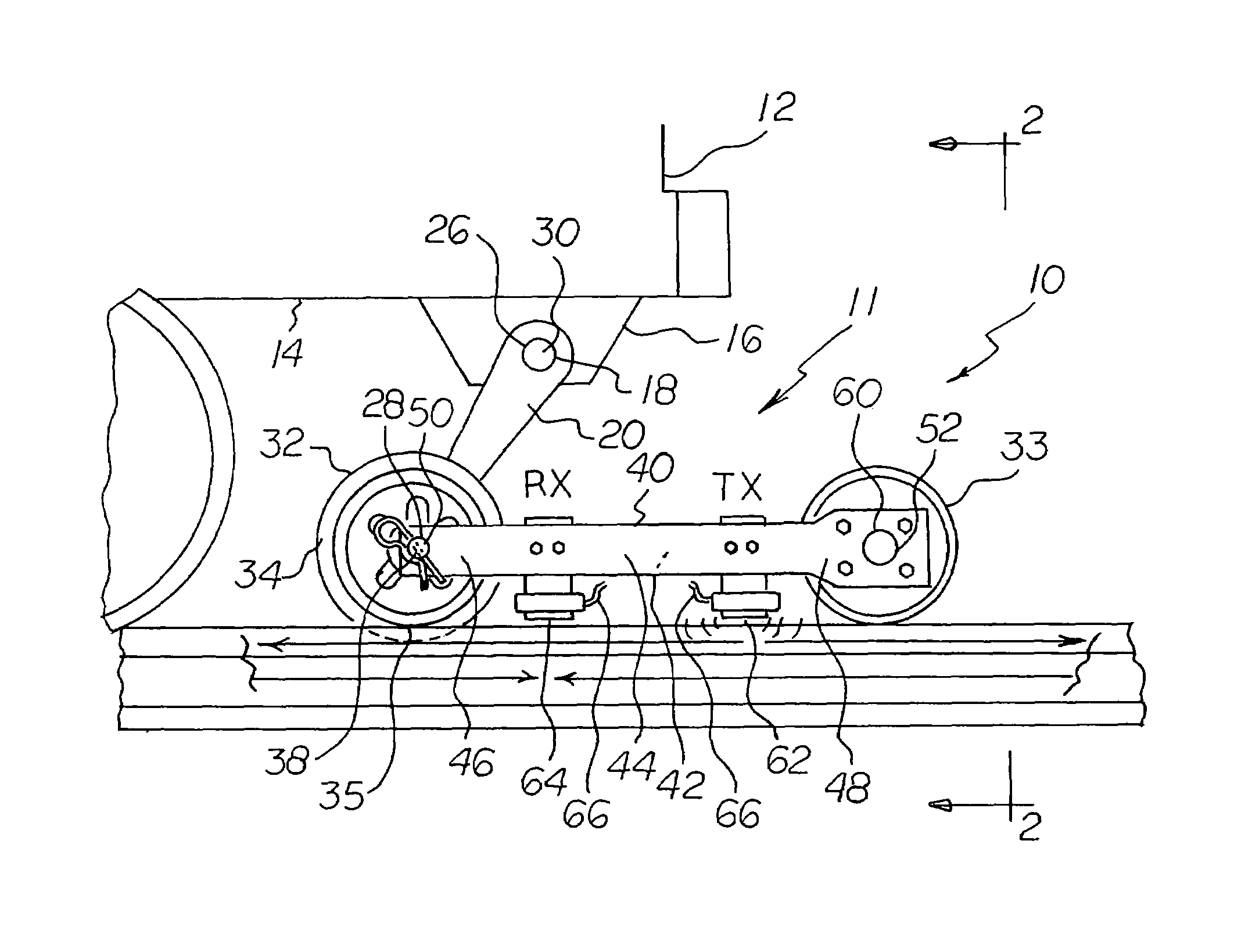
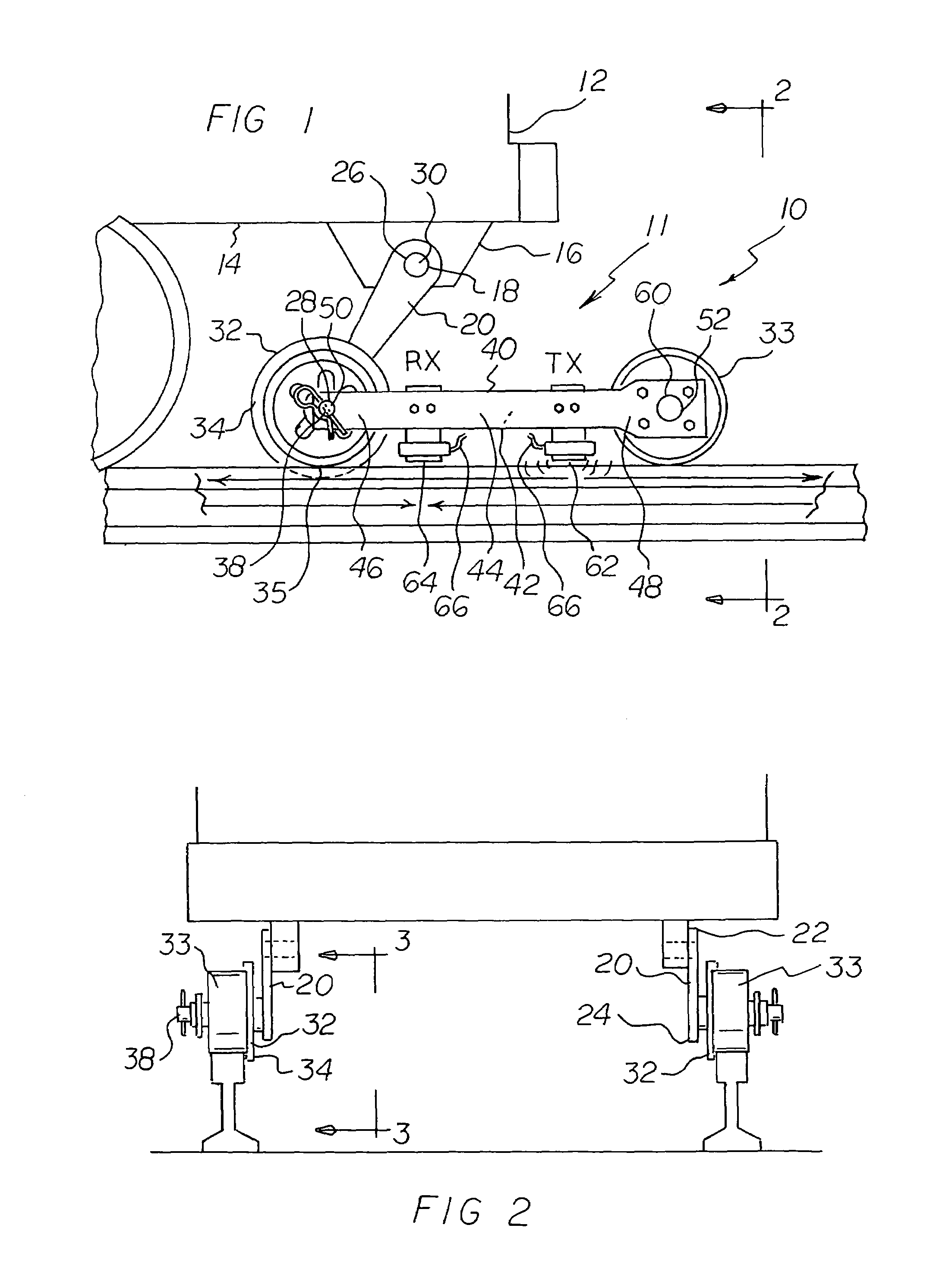
[0032]With reference now to the drawings, and in particular to FIG. 1 thereof, the preferred embodiment of the new and improved rail inspection system embodying the principles and concepts of the present invention and generally designated by the reference numeral 10 will be described.

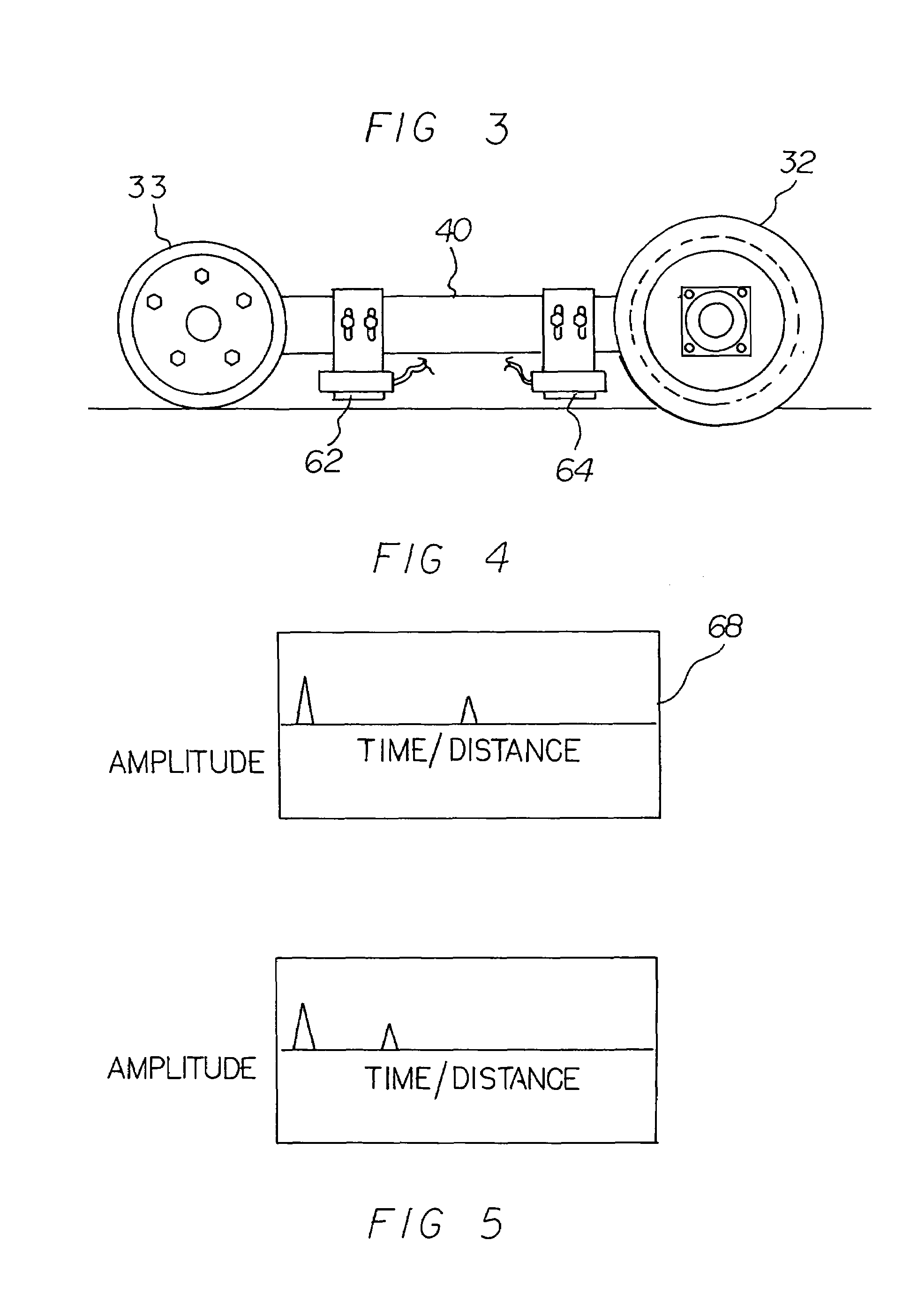
[0033]The present invention, the rail inspection system 10 is comprised of a plurality of components. Such components in their broadest context include a vehicle, a transmitter, a sensor and an electronic coupler. Such components are individually configured and correlated with respect to each other so as to attain the desired objective.

[0034]The portable direct rail inspection system allows a user to bidirectionally evaluate and detect flaws in railroad tracks.

[0035]First provided is a vehicle 12. The vehicle has an undercarriage 14 and is adapted to ride along a rail of a railroad track.

[0036]An apparatus 11 is next provided. The apparatus is coupled by an apparatus mount 16 to the guide wheel of the u...


PUM

PropertyMeasurementUnit
thicknessaaaaaaaaaa
diameteraaaaaaaaaa
dynamic rail longitudinal stress measuringaaaaaaaaaa

Abstract

An apparatus rides along a rail of a railroad track. A transmitter transmits ultrasonic guided waves bidirectionally along the rail while the apparatus and transmitter are moving along the railroad track. A sensor detects flaws in response to the transmitted ultrasonic guided waves while the apparatus, transmitter and sensor are moving along the railroad track. An electronic coupler operatively couples the sensor to monitoring equipment.

Description

BACKGROUND OF THE INVENTION[0001]1. Field of the Invention[0002]The present invention relates to a rail inspection system and more particularly pertains to bidirectionally evaluating and detecting flaws in railroad tracks.[0003]2. Description of the Prior Art[0004]The use of rail inspection systems of known designs and configurations is known in the prior art. More specifically, rail inspection systems of known designs and configurations previously devised and utilized for the purpose of detecting flaws in railroad tracks are known to consist basically of familiar, expected, and obvious structural configurations, notwithstanding the myriad of designs encompassed by the crowded prior art which has been developed for the fulfillment of countless objectives and requirements.[0005]By way of example, U.S. Pat. No. 6,262,572 issued Jul. 17, 2001, to Wojnarowski et al. discloses an electromagnetic system for railroad track crack detection and traction enhancement. U.S. Pat. No. 5,386,727 i...

Claims


Application Information

Patent Timeline
Patent Type & Authority Patents(United States)
IPC IPC(8): G01N29/04
CPCG01N29/2412G01N29/2456G01N29/265G01N2291/102G01N2291/2623
Inventor HAY, THOMAS R.HAY, ROBERTROSE, JOSEPH L.
Owner WAVESINSOLIDS
Why Eureka
Try Eureka