Golf ball

a technology of golf ball and ball, which is applied in the field of golf balls, can solve the problems of less than satisfactory improvement of disadvantageous air resistance-lowering effect, and practicable upper limit of the dimple surface coverage, and achieve the effect of increasing the distance traveled by the ball and enhancing the aerodynamic performan

Active Publication Date: 2008-06-24
BRIDGESTONE SPORTS
View PDF7 Cites 10 Cited by
  • Summary
  • Abstract
  • Description
  • Claims
  • Application Information

AI Technical Summary

Benefits of technology

[0011]It is therefore an object of the present invention to provide a golf ball which, by enhancing the aerodynamic performance due to the dimple effect, is able to increase the distance traveled by the ball.
[0014]In the present invention, by having most of the dimples formed on the surface of the ball be non-circular dimples, by having the contour lines between mutually neighboring dimples arranged so as to be substantially parallel and narrowly spaced, by having the outer surface of the lands defined by the substantially parallel contour lines coincide with the outermost peripheral face of the ball, and by finishing the inside angles of the non-circular shapes of the non-circular dimples as curves, the surface coverage by the dimples composed primarily of non-circular dimples is increased and the acutely or obtusely angled corners exhibited by the non-circular dimples are smoothly formed, imparting an air resistance-lowering effect which enables the ball to travel a longer distance.

Problems solved by technology

However, so long as circular dimples are used, the practical upper limit in the dimple surface coverage, defined as the ratio of the sum of the individual dimple surface areas to the total surface area of the spherical surface, is about 75% (that is, the surface coverage represented by the composite surface area of the lands is about 25%).
However, the small hexagonal regions demarcated by the lattice members are spherical surfaces having centers which coincide with the center of the ball and, because they are not dimples, are disadvantageous in terms of their air resistance-lowering effect.
However, in these existing golf balls, the presence of acutely or obtusely angled corners in the non-circular dimples having, for example, a polygonal shape as seen from above increases frictional resistance with air, resulting in a less than satisfactory improvement in the distance traveled by the ball.

Method used


Image

  • Golf ball
  • Golf ball
  • Golf ball

Examples


examples

[0038]Examples of the invention are given below by way of illustration, and not by way of limitation.

first embodiment

[0039]The golf ball of the invention is described more fully below in conjunction with the attached diagrams.

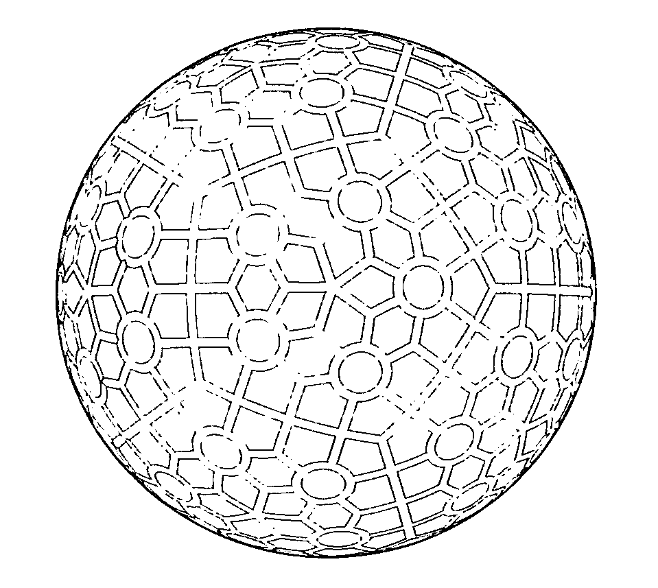
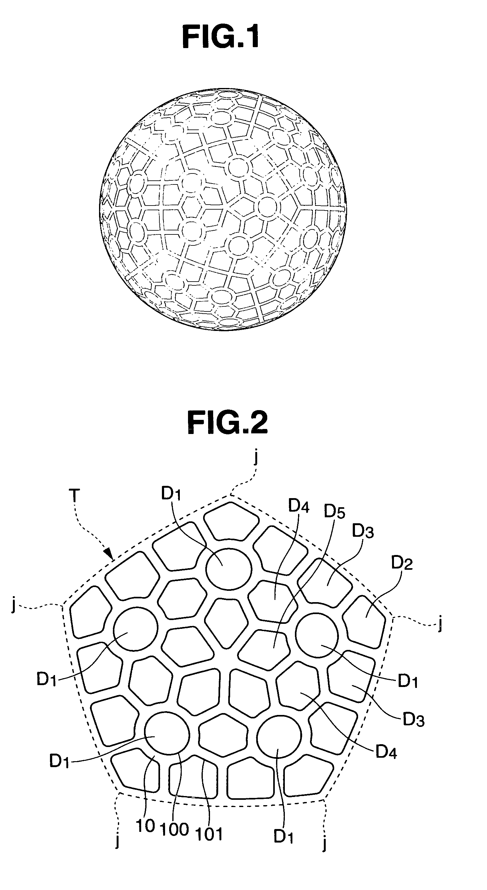
[0040]FIG. 1 is a top view showing a golf ball illustrating a first embodiment of the invention, and FIG. 2 is a partially enlarged view of the same ball. As shown in FIG. 1, this golf ball exhibits a plurality of circular dimples and non-circular dimples formed in a distinctive arrangement on the surface of the ball.

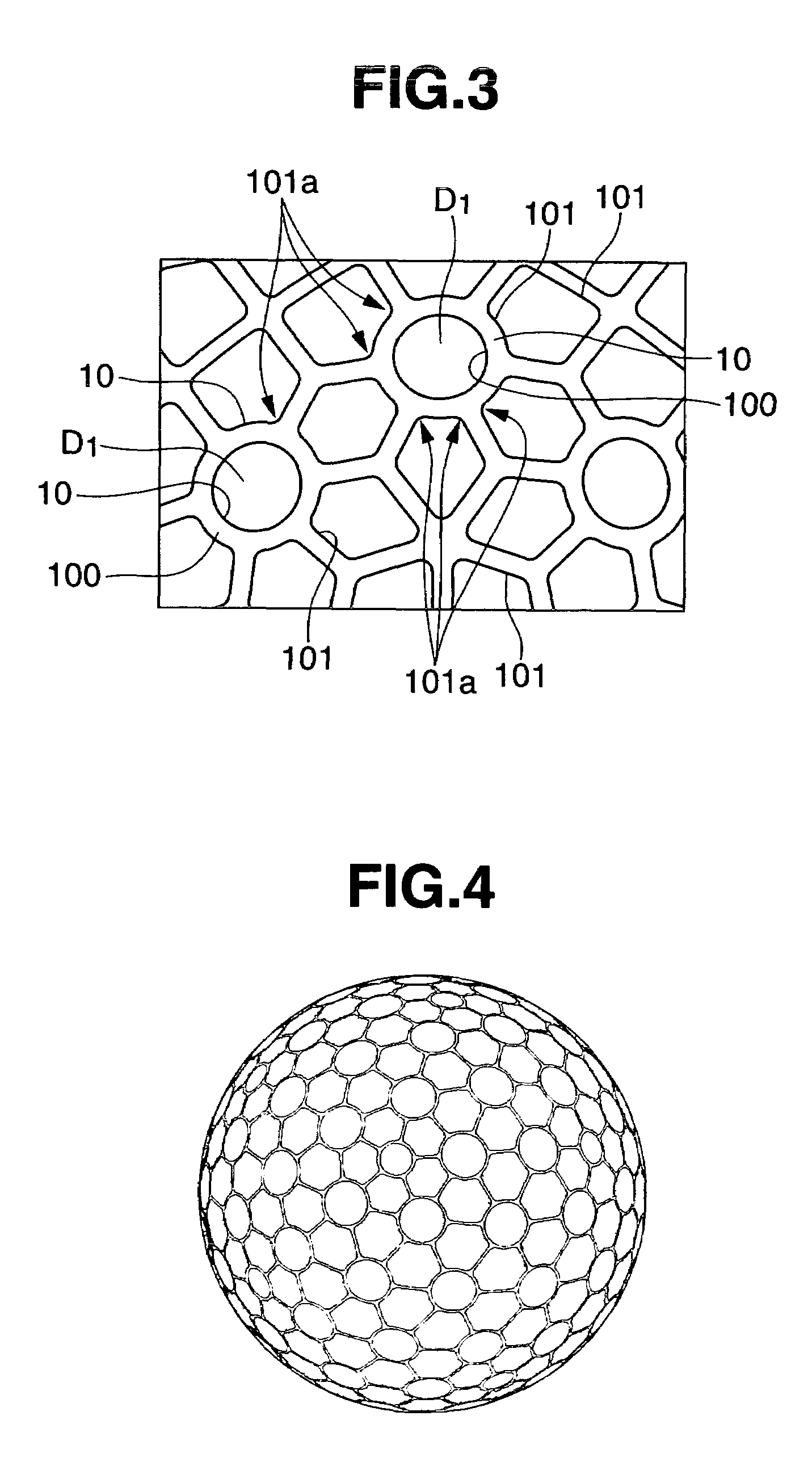
[0041]This golf ball has a dimple arrangement based on a spherical dodecahedron composed of unit pentagons T inside the five vertices of which are disposed circular dimples D1. Referring to FIG. 2, six polygonal dimples D2, D3, D3, D4, D4 and D5 are arrayed about one such circular dimple D1. The edges of the respective polygonal dimples which adjoin the circular dimple D1 exhibit circularly arcuate shapes that are parallel to circular arcs of the circular dimple D1. In the diagram, the symbol 100 represents the edge of the circular dimple, and the symbol 101 repr...

second embodiment

[0048]FIG. 4 shows the dimple arrangement pattern on a second embodiment of the inventive golf ball. At first glance, the dimples arranged on the surface of the ball all appear to be circular, providing an aesthetically pleasing appearance that does not feel strange compared with conventional golf balls on which all the dimples are circular. However, in the present invention, six non-circular dimples are always arranged around a circular dimple, and there are no mutually neighboring circular dimples. That is, the circular dimples used on the golf ball of this second embodiment are of two types, one (D10) having a large diameter of 4.3 mm and the other (D20) having a small diameter of 3.3 mm. As shown in FIG. 5, a pair of substantially hexagonal dimples D40 and D40 are disposed between a large-diameter circular dimple D10 and a small-diameter circular dimple D20 so as to fill the intervening gap. A slender, narrow-width land 10 is formed between the large-diameter circular dimples D1...


PUM


Abstract

The invention provides a golf ball with a ball surface having a plurality of non-circular dimples thereon, wherein mutually neighboring dimples have contour lines therebetween which are arranged so as to be substantially parallel and are separated by an interval of 0.05 to 1.0 mm, land areas defined by the substantially parallel contour lines have an outer surface which forms the outermost peripheral face of the ball, and the non-circular dimples have a non-circular shape with inside angles that are curved. This arrangement endows the ball with a distinctive, aesthetically pleasing appearance on account of the dimple pattern composed largely of non-circular dimples. Moreover, even though numerous non-circular dimples are arranged on the surface of the ball, the high surface coverage and air resistance-lowering effect enable the distance traveled by the ball to be increased.

Description

BACKGROUND OF THE INVENTION[0001]The present invention relates to a golf ball on the surface of which many of the dimples formed are of non-circular shape, which golf ball has an excellent flight performance.[0002]For a golf ball which has been hit to travel a long distance, it is important that the ball itself have a high rebound and that air resistance during flight be reduced by dimples arranged on the surface of the ball. A variety of methods for arranging dimples uniformly and to the highest possible density on the surface of the ball have been proposed in order to reduce the air resistance.[0003]Here, the commonly employed dimple shape is a recess that is circular as seen from directly above. Because such circular dimples are used, attempts to arrange circular dimples to a high density, such as by making the width of the land between two neighboring circular dimples as close to zero as possible, result in the formation of triangular or quadrangular lands of a given size in are...

Claims


Application Information

Patent Timeline
Patent Type & Authority Patents(United States)
IPC IPC(8): A63B37/12
CPCA63B37/0004A63B37/0006A63B37/0009A63B37/0017A63B37/0018A63B37/0019A63B37/002A63B37/0021A63B37/0007A63B37/0012A63B37/00215
Inventor KASASHIMA, ATSUKISATO, KATSUNORI
Owner BRIDGESTONE SPORTS
Why Eureka
Try Eureka