Eureka AIR delivers breakthrough ideas for toughest innovation challenges, trusted by R&D personnel around the world.

Car-used lock with alerting function

a technology of alerting function and car locks, which is applied in the field of multifunctional car locks, can solve the problem of not being able to effectively prevent the thief from stealing the car, and achieve the effect of avoiding the busy line of the car owner's phon

Inactive Publication Date: 2008-06-24
WANDER HLDG GRP
View PDF2 Cites 2 Cited by
  • Summary
  • Abstract
  • Description
  • Claims
  • Application Information

AI Technical Summary

Benefits of technology

[0003]Accordingly, the primary object of the present invention is to provide a multi-functional car lock, wherein the lock is effective in the thief-proof. The present invention has the affect of immediate alert and communication with legal frequency bands and power. The power source is from the car used handset. No additional battery is necessary. Furthermore, two sets of quick dialing numbers are used so that the line's busy of the car owner's phone can be avoided.
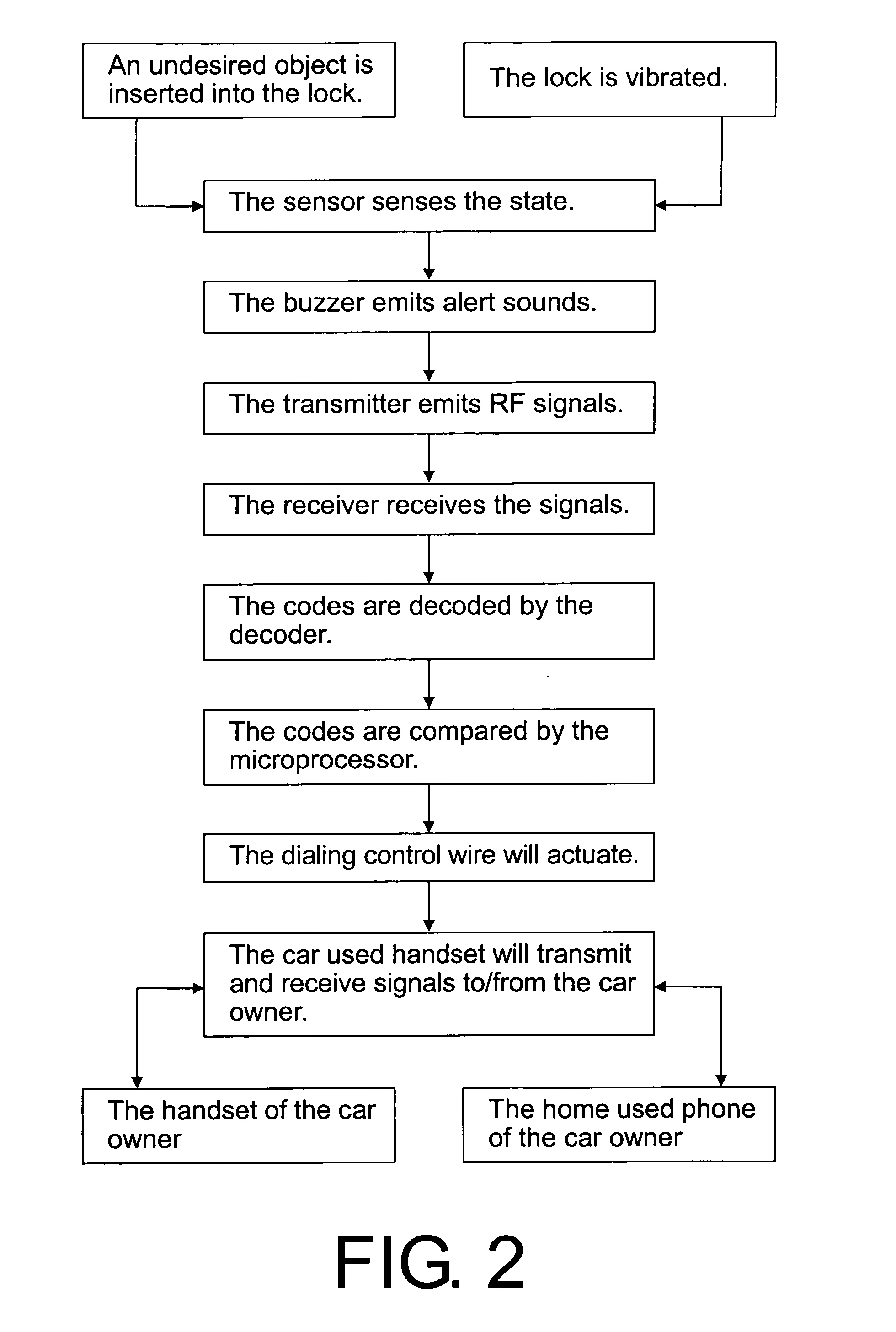
[0004]To achieve above object, the present invention provides a car-used lock with alerting function which comprises a lock installed with a sensor, a buzzer and a transmitter; a receiving control device for receiving signals from the transmitter; the receiving control device Furthermore, installed with a receiver, a decoder, a microprocessor, an indicator, leaning keys, a dialing control wire and a power source; a car-used handset connected to the receiving control device and having a battery. The receiver serves to transfer the high frequency signals emitted from the transmitter into digital signals. The decoder serves to transfer the digital signals into codes. The microprocessor serves to compare the codes with the built-in data. The lock has the affect of immediate alert and communication with legal frequency bands and power. The power source is from the car used handset. Furthermore, two sets of quick dialing numbers are used so that the occupation of line of the car owner can be avoided.

Problems solved by technology

However above-mentioned way cannot effectively prevent the thief to steal the car.

Method used


Image

  • Car-used lock with alerting function
  • Car-used lock with alerting function
  • Car-used lock with alerting function

Examples


Embodiment Construction

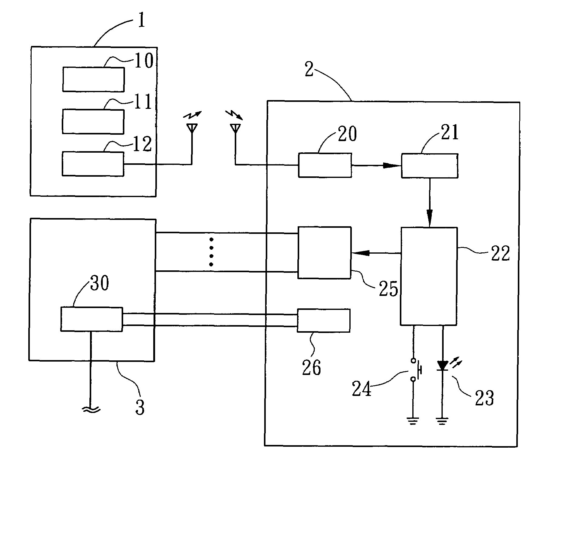
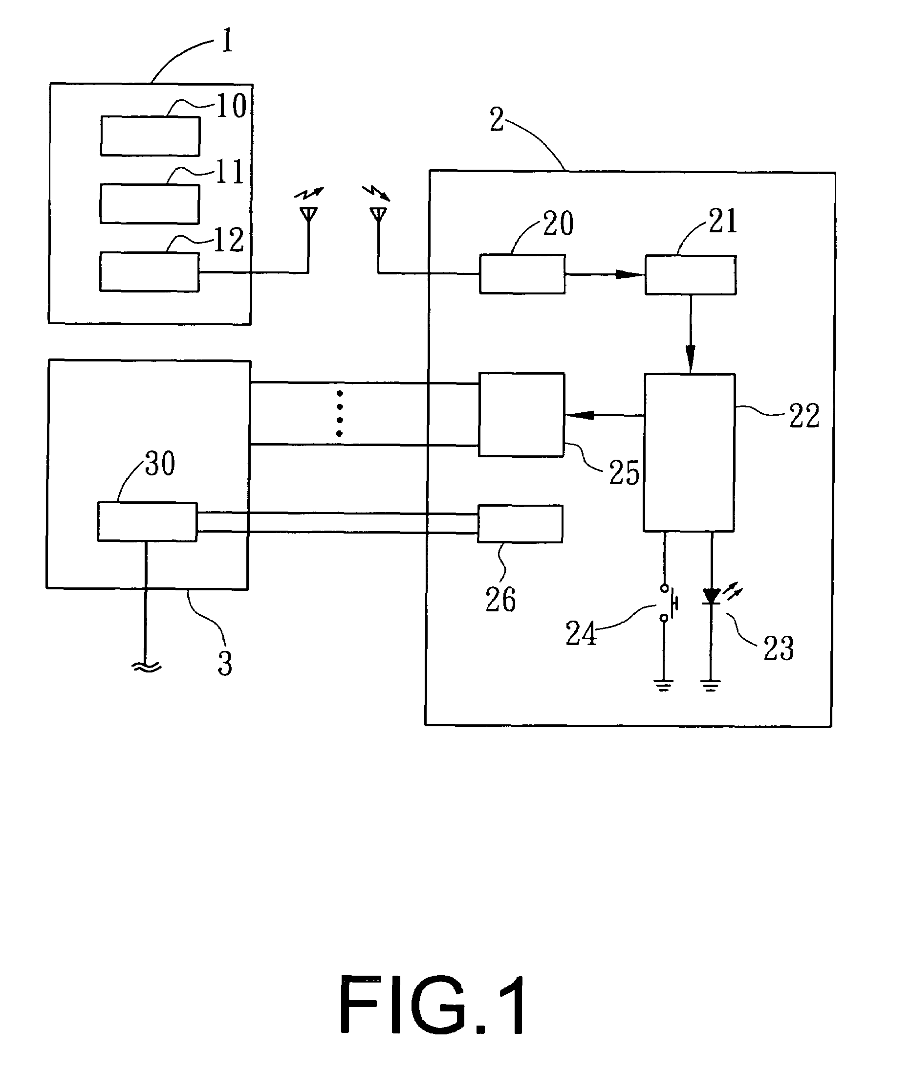
[0008]In order that those skilled in the art can further understand the present invention, a description will be described in the following in details. However, these descriptions and the appended drawings are only used to cause those skilled in the art to understand the objects, features, and characteristics of the present invention, but not to be used to confine the scope and spirit of the present invention defined in the appended claims. Referring to FIG. 1, the elements of the present invention will be described herein.

[0009]A lock 1 is installed with a sensor 10, a buzzer 11 and a transmitter 12.

[0010]A receiving control device 2 receives signals from the transmitter 12. The receiving control device 2 is installed with a receiver 20, a decoder 21, a microprocessor 22, an indicator 23, a leaning key 24, a dialing control wire 25 and a power source 26. The receiver 20 serves to convert the high frequency signals emitted from the transmitter 12 into digital signals. The decoder 21...


PUM


Abstract

A car-used lock with alerting function comprises a lock installed with a sensor, a buzzer and a transmitter; a receiving control device for receiving signals from the transmitter; the receiving control device being installed with a receiver, a decoder, a microprocessor, an indicator, leaning keys, a dialing control wire and a power source; a car-used handset connected to the receiving control device and having a battery. The receiver serves to transfer the high frequency signals emitted from the transmitter into digital signals. The decoder serves to transfer the digital signals into codes. The microprocessor serves to compare the codes with the built-in data. The lock has the affect of immediate alert and communication with legal frequency bands and power. The power source is from the car used handset. Furthermore, two sets of quick dialing numbers are used so that the line busy of the car owner can be avoided.

Description

FIELD OF THE INVENTION[0001]The present invention relates to car-used locks, and in particular to a multi-functional car lock, wherein the lock is effective in the thief-proof. The present invention has the affect of immediate alert and communication with legal frequency bands and power. The power source is from the car used handset. No additional battery is necessary. Furthermore, two sets of quick dialing numbers are used so that the line's busy of the car owner's phone can be avoided.BACKGROUND OF THE INVENTION[0002]Currently door lock is assembled to a steering wheel of the car so that the thief cannot rotate the steering wheel. Or the door lock is assembled to a gear switch of a car so that the gear switch cannot be operated. Or the door lock is assembled the oil treadle so that the thief cannot trading the oil treadle to drive the car. However above-mentioned way cannot effectively prevent the thief to steal the car.SUMMARY OF THE INVENTION[0003]Accordingly, the primary object...

Claims


Application Information

Patent Timeline
Patent Type & Authority Patents(United States)
IPC IPC(8): B60R25/10
CPCB60R25/1004B60R25/102B60R2325/205
Inventor HSIEH, HUI-HUA
Owner WANDER HLDG GRP
Why Eureka
Eureka Blog
Learn More