Method of sending information through a tree and ring topology of a network system

a network system and information technology, applied in the field of sending information through a tree topology or a ring topology of a network system, can solve the problems of high operational overhead, inability to statistically share capacity, and limited and relatively expensive capacity of tdm circuits, so as to avoid the bottleneck of tdm system, reduce the cost, and improve the effect of efficiency

Inactive Publication Date: 2008-06-24
ADVA OPTICAL NETWORKING SE
View PDF4 Cites 202 Cited by
  • Summary
  • Abstract
  • Description
  • Claims
  • Application Information

AI Technical Summary

Problems solved by technology

This TDM circuit, with limited and relatively expensive capacity, is a bottleneck.
The access circuit is provisioned separately from the provisioning of the network service, such as an IP service, leading to high operational overhead.
When several circuits are aggregated in the TDM access network, statistical sharing of capacity is not possible due to the fixed nature of TDM circuits.
The channelized TDM interfaces include complex hardware that monitors each circuit individually but makes line cards expensive.
However, these automatic features become problematic in large scale operator environments.
In summary, problems with basic Ethernet switches include: no support for customer separation; low degree of security due to the fact that cross traffic directly between end-customers is allowed; dynamic address learning may open up for DoS attacks; and requires distributed element management and service creation due to the fact that a potential large set of distributed units needs to be configured and managed; and the standard based Spanning Tree Protocol (STP) based restoration is slow.

Method used


Image

  • Method of sending information through a tree and ring topology of a network system
  • Method of sending information through a tree and ring topology of a network system
  • Method of sending information through a tree and ring topology of a network system

Examples


Embodiment Construction

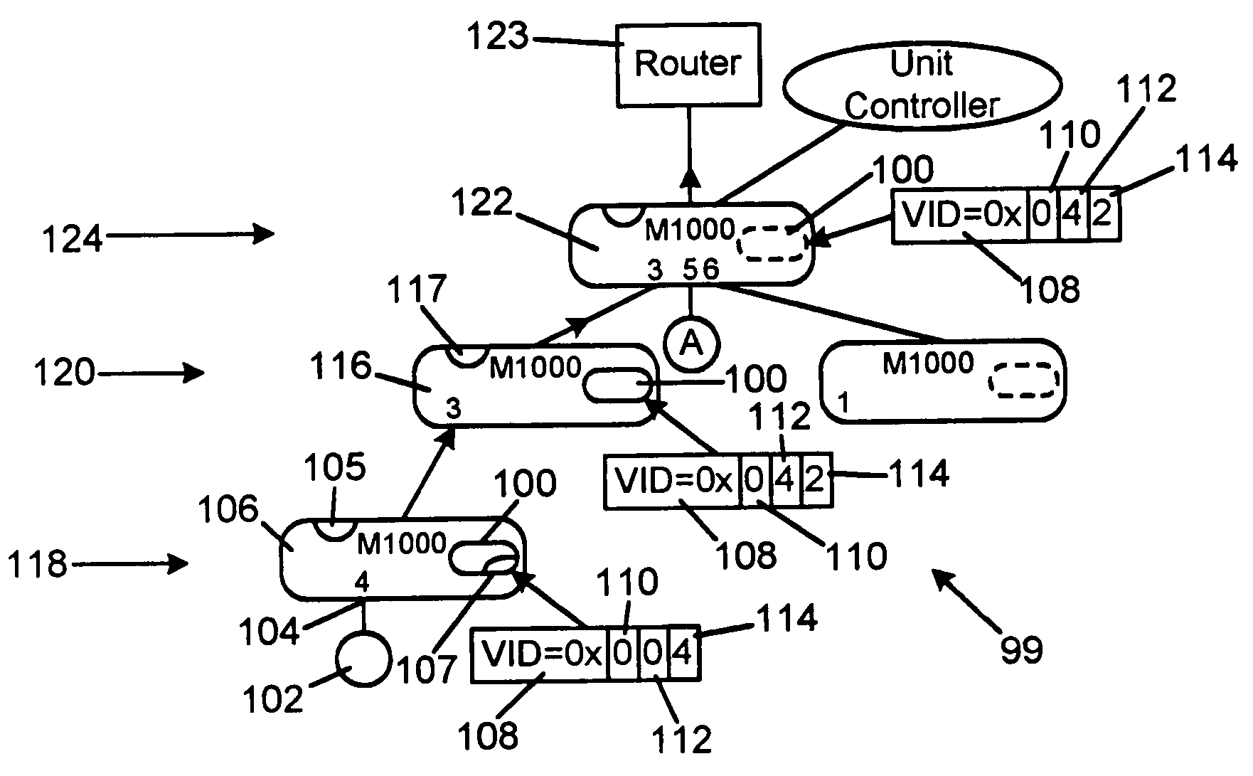
[0025]In general, the method of the present invention includes steps for sending information up and down a tree topology of nodes in a network. The method also covers the steps of sending information in a ring topology of nodes. The method includes steps of adding a tag and port numbers when the packet moves upwardly in a tree topology towards edge equipment such as a router or a switch, i.e. in an ingress direction, so that each node shifts previous port numbers and adds a port number before forwarding the packet. When the packet moves from a router or switch downwardly in the tree topology, i.e. in an egress direction, each node removes a port number, such as the port number of the departure port, from the tag and shifts the subsequent port numbers within the tag. The invention is not limited to shifting the port numbers between nibbles. It is also possible to merely add and remove port numbers and other identification information from the nibbles without shifting such information...


PUM


Abstract

The method is for sending information through a topology. A first and second node each having a first node having a first access port, a second access port and a first uplink connected to a first router and a second router, respectively. A third node is provided that has a first access port and a first uplink, the first uplink of the third node being connected to the second access port of the first node. A first packet is sent via the first access port to the second node. The second node adds a first port number to a tag of the first packet and sends the first packet via the first uplink of the second node to the first access port of the first node. The first node receives the first packet via the first access port of the first node. The first node adds the first port number to the tag and adds a first port number of the first access port of the first node to the tag. The first node sends the first packet via the first uplink of the first node to a first router.

Description

PRIOR APPLICATION[0001]This is a continuation-in-part patent application of U.S. patent application Ser. No. 10 / 707,916, filed 23 Jan. 2004.TECHNICAL FIELD[0002]The method of the present invention relates to sending information through a tree topology or a ring topology of a network system.BACKGROUND AND SUMMARY OF INVENTION[0003]Metro networks are often organized in two levels including metro access and metro core systems. Metro access networks are deployed near the end customer while metro core networks aggregate several access networks deployed in different parts of the metro area. The metro core systems also host the gateway(s) to the wide area backbone network. Currently the dominating technology to connect individual customers and businesses to the Internet is a leased 1.5 or 2.0 Mbps TDM circuits from the customer premises to the provider edge node, that is, router or a switch located in the point-of-presence (POP). The edge equipment is populated with channelized TDM interfa...

Claims


Application Information

Patent Timeline
Patent Type & Authority Patents(United States)
IPC IPC(8): H04L12/56H04L12/24H04L12/28
CPCH04L12/4645H04L41/12H04L45/00H04L45/48H04L45/76
Inventor ORAVA, FREDRIKRAMFELT, LARS
Owner ADVA OPTICAL NETWORKING SE
Why Eureka
Try Eureka