Self boosting packing element

a packing element and self-boosting technology, applied in the direction of sealing/packing, fluid removal, borehole/well accessories, etc., can solve the problems of limited design and no solutions, and achieve the effect of enhancing the friction force for adhesion of the element to the mandrel

Active Publication Date: 2008-07-01
BAKER HUGHES INC
View PDF27 Cites 86 Cited by
  • Summary
  • Abstract
  • Description
  • Claims
  • Application Information

AI Technical Summary

Benefits of technology

[0056]A packer assembly features one or more elements that preferably swell when in contact with well fluids and have a feature in them that responds to an applied load in a given direction by retaining such a boost force with a locking mechanism. A single element can have two such mechanisms that respond to applied forces from opposed directions. Friction force for adhering the element to the mandrel is enhanced with surface treatments between them that still allow the locking mechanisms to operate.

Problems solved by technology

These designs were still limited to the amount of swelling from the sealing element as far as the developed contact pressure against the surrounding tubular or wellbore.
In some designs there were also issues of extrusion of the sealing element in a longitudinal direction as it swelled radially but no solutions were offered.

Method used


Image

  • Self boosting packing element
  • Self boosting packing element

Examples


Embodiment Construction

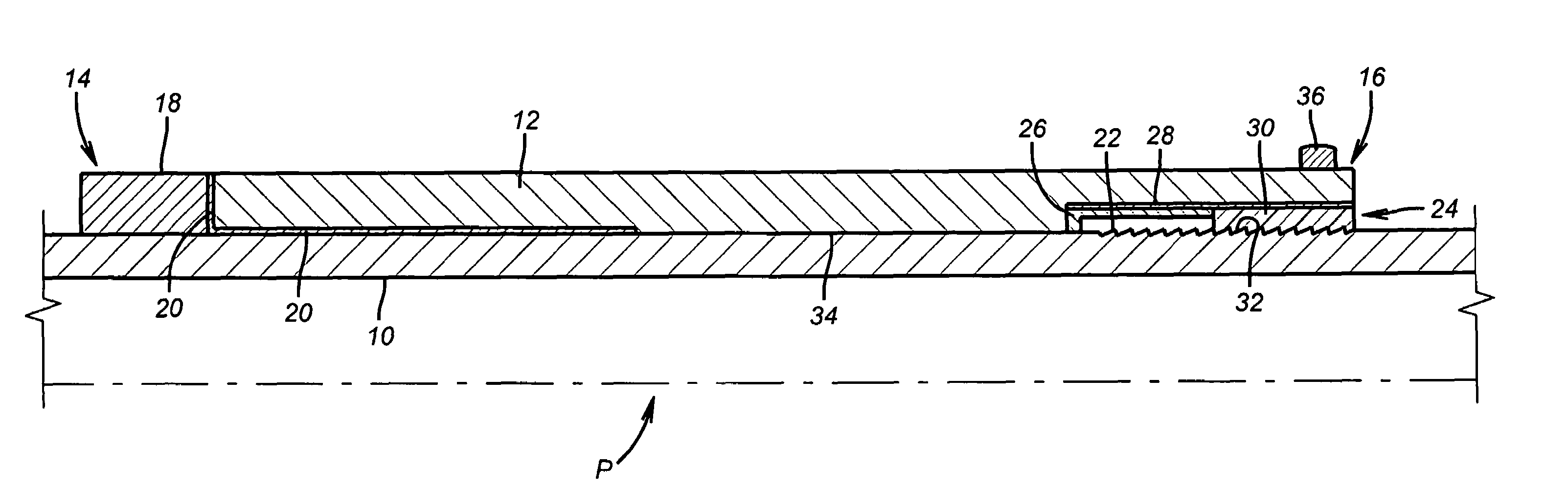
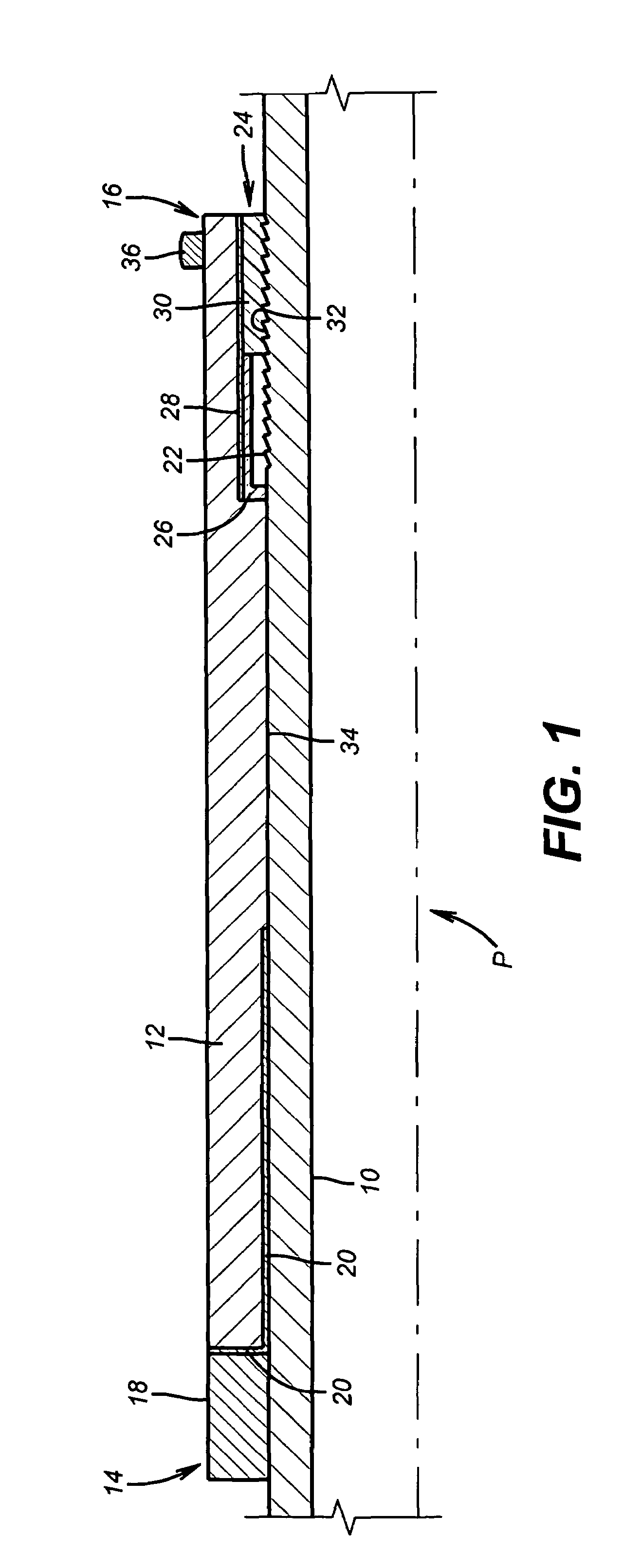
[0058]FIG. 1 will be used to illustrate a variety of variations of the present invention. What is illustrated in the Figure is a mandrel 10 for a packer P. Mounted to the mandrel 10 is an element 12 that preferably is of the type that swells in contact with well fluids using materials described in the patents and applications discussed above. A covering (not shown) can also be applied to the element 12 to provide a time delay to allow the packer P to be positioned close to where it needs to be set. The materials that accomplish this delay using a cover that goes away after a time exposure to well fluids and predetermined temperatures are also discussed in the patents and applications above.

[0059]In the Figure, the element assembly 12 has an uphole end 14 and a downhole end 16. In one variation that is shown, the uphole end 14 is abutting a block 18 and is further secured to it and between itself and mandrel 10 with an adhesive or some type of bonding material 20 compatible with well...


PUM


Abstract

A packer assembly features one or more elements that preferably swell when in contact with well fluids and have a feature in them that responds to an applied load in a given direction by retaining such a boost force with a locking mechanism. A single element can have two such mechanisms that respond to applied forces from opposed directions. Friction force for adhering the element to the mandrel is enhanced with surface treatments between them that still allow the locking mechanisms to operate.

Description

FIELD OF THE INVENTION[0001]The field of this invention is generally plugs and packers for downhole use and more particularly packers that have a sealing element that swells and retains boost forces when subjected to pressure differentials.BACKGROUND OF THE INVENTION[0002]Packers and plugs are used downhole to isolate zones and to seal off part of or entire wells. There are many styles of packers on the market. Some are inflatable and others are mechanically set with a setting tool that creates relative movement to compress a sealing element into contact with a surrounding tubular. Generally, the length of such elements is reduced as the diameter is increased. Pressure is continued from the setting tool so as to build in a pressure into the sealing element when it is in contact with the surrounding tubular.[0003]More recently, packers have been used that employ elements that respond to the surrounding well fluids and swell to form a seal. Many different materials have been disclosed...

Claims


Application Information

Patent Timeline
Patent Type & Authority Patents(United States)
IPC IPC(8): E21B23/06
CPCE21B33/1277E21B33/1208
Inventor MURRAY, DOUGLAS J.BERZIN, VEL
Owner BAKER HUGHES INC
Why Eureka
Try Eureka