CMM arm with exoskeleton
a technology of exoskeleton and arm, which is applied in the direction of mechanical measuring arrangement, program control, instruments, etc., can solve the problems of limited accuracy and high manufacturing cost, and achieve the effect of less bends, greater section and more accura
- Summary
- Abstract
- Description
- Claims
- Application Information
AI Technical Summary
Benefits of technology
Problems solved by technology
Method used
Image
Examples
first embodiment
Portable Robot CMM Arm
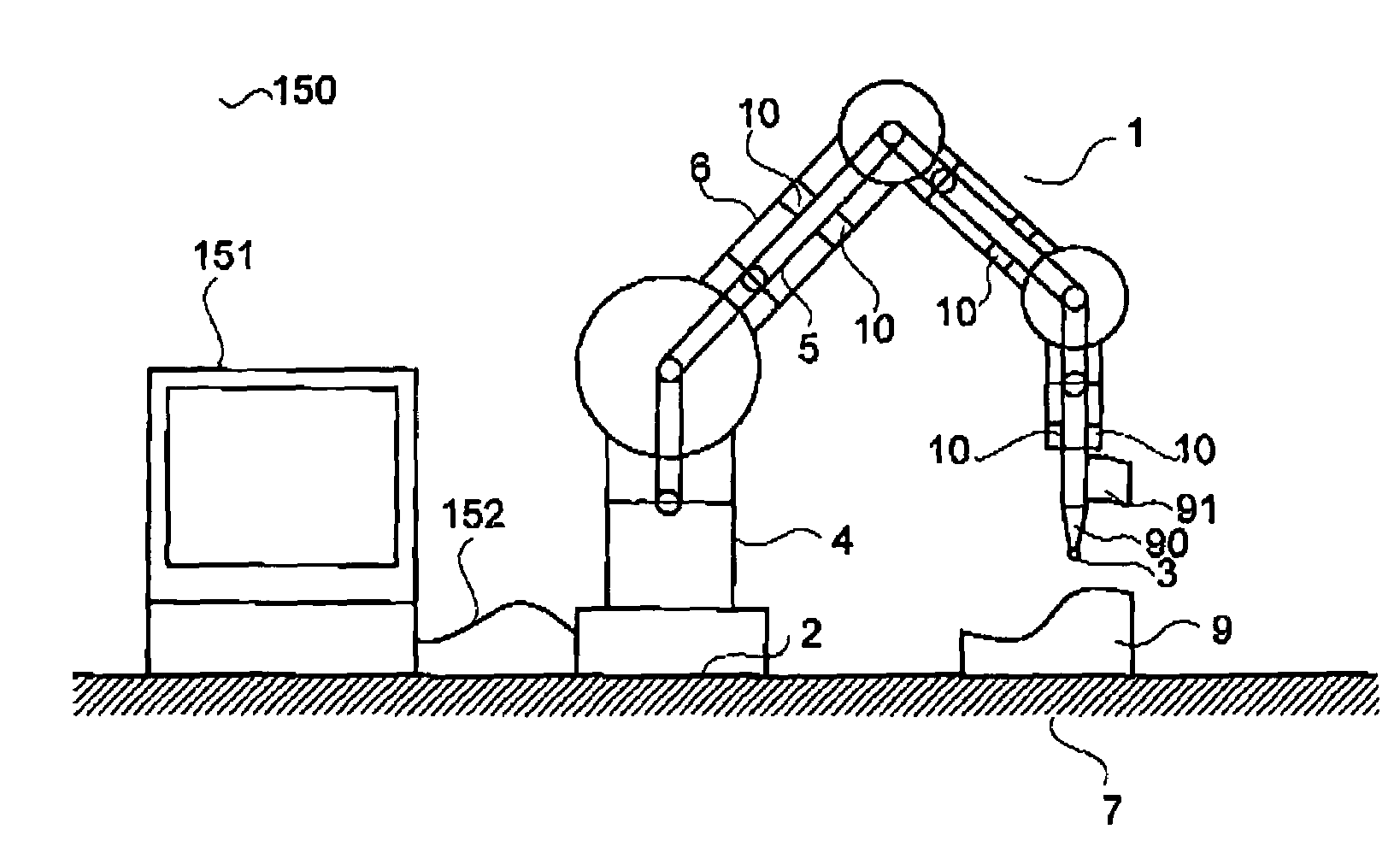
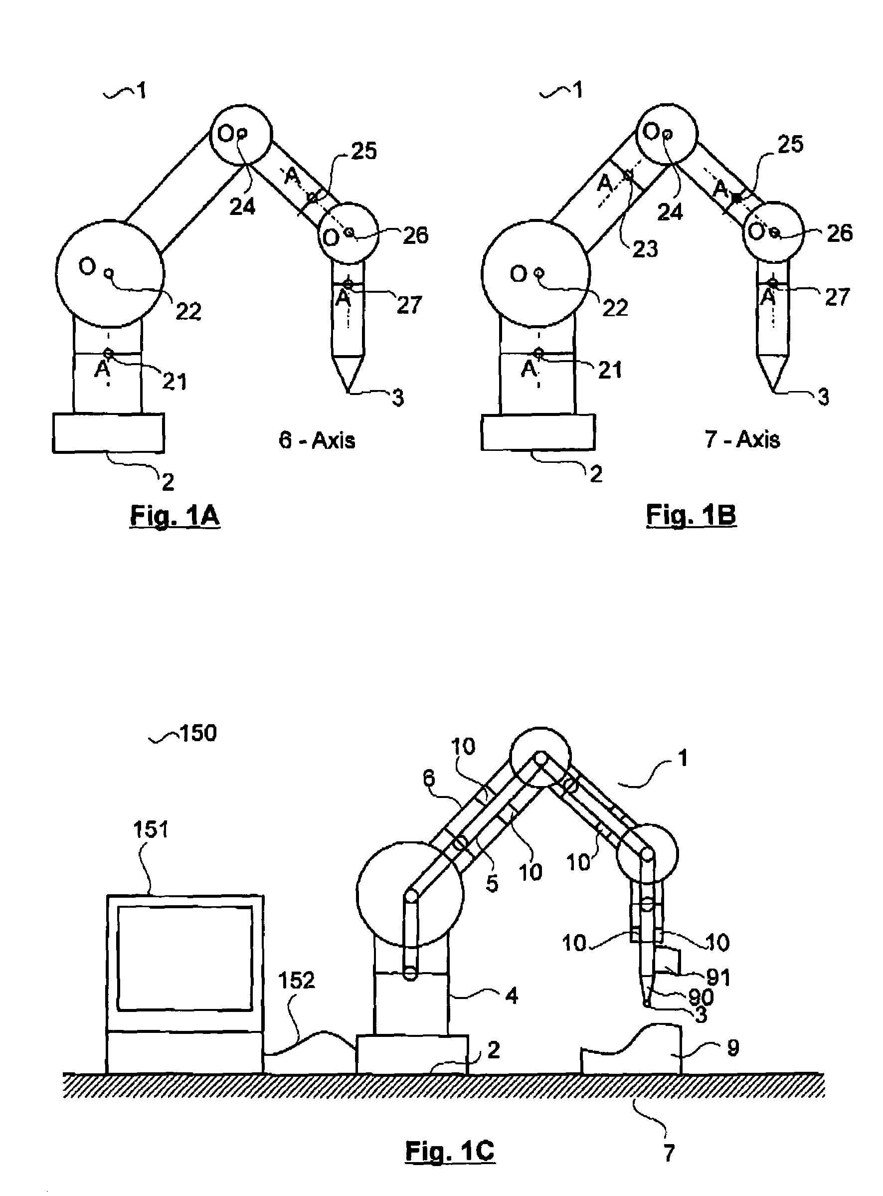
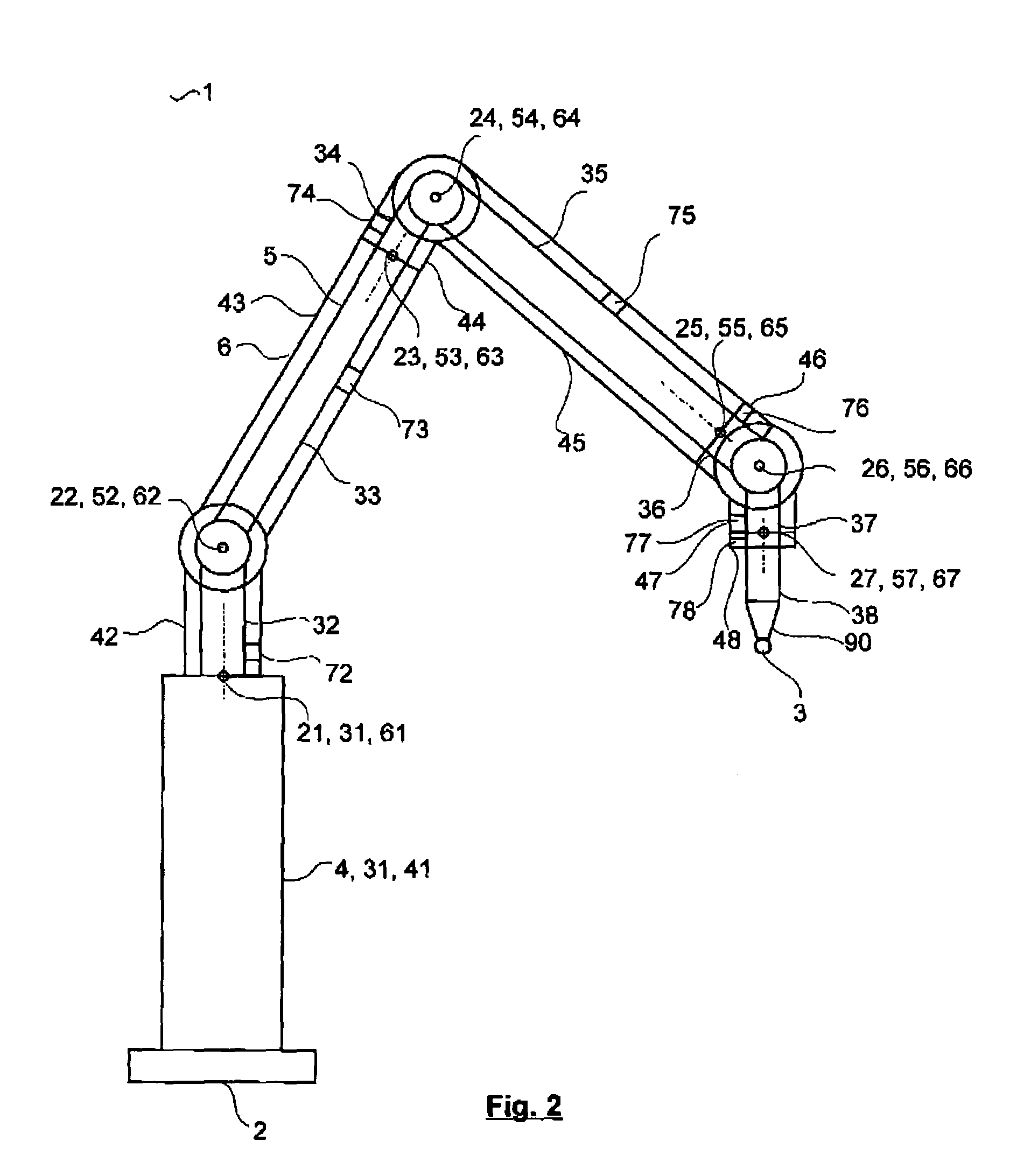
[0186]The first embodiment of this CMM Arm with Exoskeleton invention is a Portable Robot CMM Arm. This Portable Robot CMM Arm embodiment comprises an Internal CMM Arm guided by an Exoskeleton. The Exoskeleton supports and manipulates the Internal CMM Arm via transmission means such that it can measure accurately. This invention can be embodied in many Robot CMM Arm articulated arm layouts. There are two preferable layouts for a Robot CMM Arm in accordance with a first embodiment of the present invention: 6-axis with 6 joints and 7-axis with 7 joints.
Robot CMM Arm Joint and Segment Layout
[0187]FIGS. 1A and 1B are diagrams showing the preferable 6-axis and 7-axis layouts respectively for a Robot CMM Arm 1 in accordance with a first embodiment of the present invention. An articulated Robot CMM Arm 1 has a base end 2 and a probe end 3 and comprises a series of segments and rotating joints between the two ends. There are two types of joint: axial and orthogonal. An...
second embodiment
Industrial Robot CMM Arm
[0458]In this second embodiment, an Industrial Robot CMM Arm is disclosed for providing accurate robot movement. In this second embodiment, there is provided a seven-axis Industrial Robot CMM Arm with a common base segment1 and a common probe segment8. The common probe segment can carry a heavy probe or tool and be subject to significant force whilst providing accurate position information. The Industrial Robot CMM Arm not only has better repeatability than existing industrial robots, but is also of the order of 10 times more accurate. Referring now to FIG. 53, the Industrial Robot CMM Arm 450 has a common base 4 that comprises CMM Segment131, Transmission Means171 and Robot Exoskeleton Segment141. The Industrial Robot CMM Arm 450 also has a common probe segment8451 that comprises CMM Segment838, Transmission Means878 and Exoskeleton Segment848. In effect, this provides a Transmission Means878 that is rigid. CMM Segments2-732-37 of the Industrial Robot CMM ar...
third embodiment
[0509]In this third embodiment, an Actively Supported Robot CMM Arm is disclosed that has substantially reduced forces and moments acting on the joints and segments of the Internal CMM Arm 5 in all the spatial layouts to which it can be moved.
Forces and Moments on the Robot CMM Arm of the First Embodiment
[0510]At some spatial layouts of the Robot CMM Arm 1, there are significant loads on the Internal CMM Arm 5 such that the provided arrangement of seven motors 176 that act through the seven Exoskeleton Joints1-761-67 of the Exoskeleton 6 do not provide sufficient control outputs to reduce these loads. In some spatial layouts, all the weight of the following segments of the Internal CMM Arm 5 acts on a joint. For example, when the Internal CMM Arm 5 is in a vertical spatial layout, the combined weight of CMM Segments2-832-38 bears directly down onto CMM Joint151. Similarly, the combined weight of CMM Segments3-833-38 bears directly down onto CMM Joint252 and similarly for CMM Joint35...
PUM
 Abstract
Description
Claims
Application Information
 - R&D
- Intellectual Property
- Life Sciences
- Materials
- Tech Scout
- Unparalleled Data Quality
- Higher Quality Content
- 60% Fewer Hallucinations
Browse by: Latest US Patents, China's latest patents, Technical Efficacy Thesaurus, Application Domain, Technology Topic, Popular Technical Reports.
© 2025 PatSnap. All rights reserved.Legal|Privacy policy|Modern Slavery Act Transparency Statement|Sitemap|About US| Contact US: help@patsnap.com


