Method and sensor setup for determination of deflection and/or strain for failure detection

a technology of failure detection and sensor setup, which is applied in the direction of electrical/magnetic measuring arrangement, machine/engine, wind energy generation, etc., can solve the problems of system cost and system strain, and achieve the effect of more robust measuremen

Inactive Publication Date: 2011-12-13
SIEMENS AG
View PDF8 Cites 1 Cited by
  • Summary
  • Abstract
  • Description
  • Claims
  • Application Information

AI Technical Summary

Benefits of technology

[0012]The use of an inflexible support has the advantage that only a relatively small distance between the second point and a third point needs to be measured when the distance between the first and second point changes since the third point has a fixed and known relationship to the first point due to the inflexible support. The relatively small distance to be measured increases the accuracy and the robustness of the determination of the deflection and / or the strain.
[0030]As the deflection and / or the strain is determined by means of the inventive method or by means of any of the inventive devices, the obtained result has the following qualities: the measurement is significantly more robust regarding local geometry. Furthermore, the measurement is more robust due to large dynamic range in the proximity measurement.

Problems solved by technology

For example, the tower of a wind turbine as well as the wind turbine rotor blades may be exposed by strong wind which causes a strain on the tower and the rotor blades.
Such systems are rather expensive.

Method used


Image

  • Method and sensor setup for determination of deflection and/or strain for failure detection
  • Method and sensor setup for determination of deflection and/or strain for failure detection
  • Method and sensor setup for determination of deflection and/or strain for failure detection

Examples


Embodiment Construction

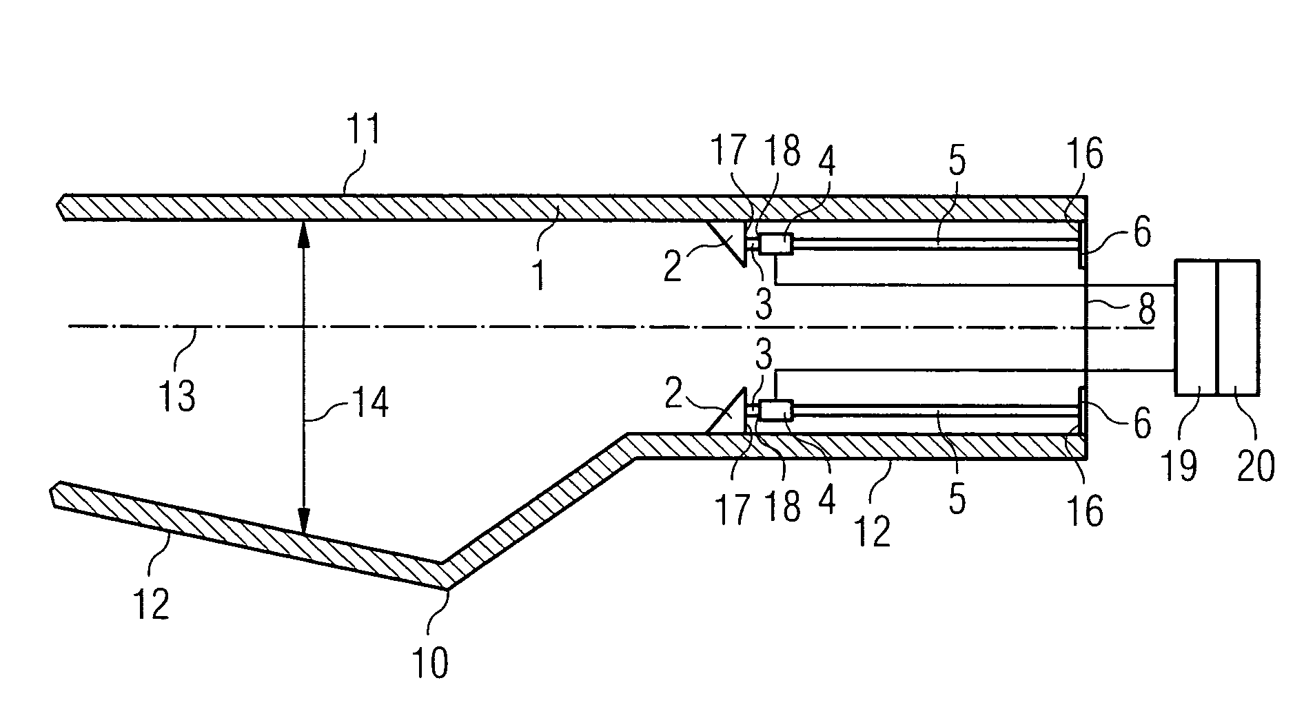
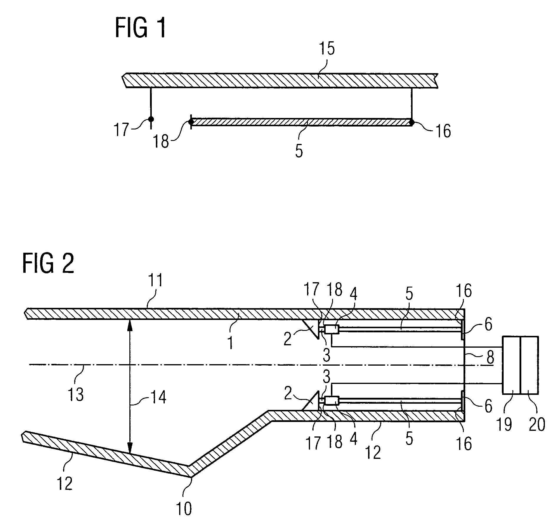
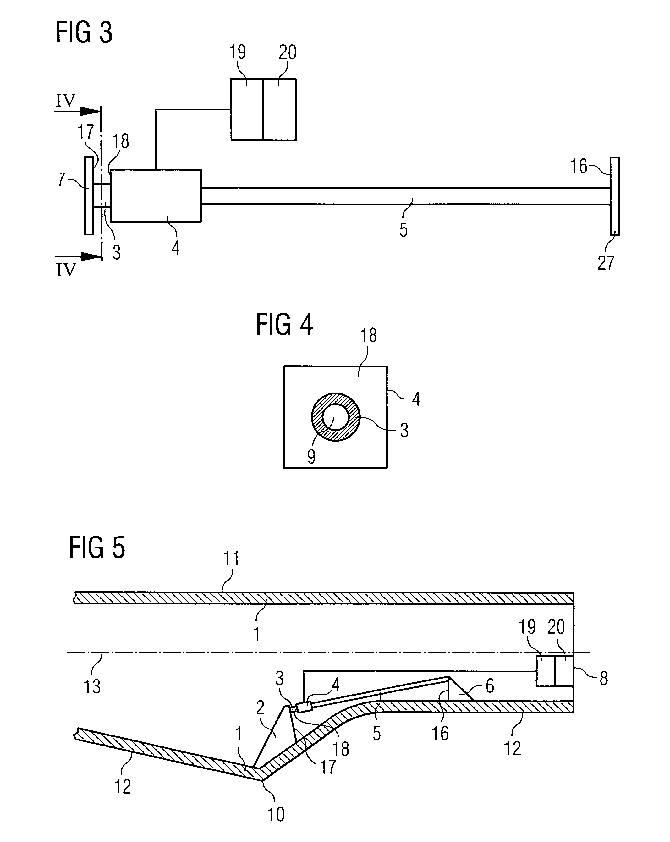
[0037]An embodiment of the present invention will now be described with reference to FIGS. 1 to 5. At first, the general principle or the idea of the invention will be explained with reference to FIG. 1. FIG. 1 schematically shows an elongated member of a wind turbine 15 which is not deflected in a sectional view. The elongated member 15 comprises two distant points, a first point 16 and a second point 17. It further comprises a third point 18 which is connected to the first point 16 by means of an elongated inflexible or stiff support 5, for example a stiff rod. In FIG. 1 the inflexible support 5 extends parallel to the elongated member 15. Moreover, the third point 18 is located between the first point 16 and the second point 17. The distance between the first point 16 and the third point 18 is much longer than the distance between the second point 17 and the third point 18. In case of a deflection of the elongated member 15, the distance between the first point 16 and the second ...


PUM


Abstract

A method for determining the deflection and / or strain of an elongated member of a component is provided, in which a first point and a second point are assigned to the same side of an elongated member of the component, wherein the deflection and / or strain of the elongated member is determined by determining the distance between the second point and a third point, which is connected to the first point by an inflexible support, whereby the distance between the first point and the third point is considerably longer than the distance between the second point and the third point, and wherein the distance between the second point and the third point is determined in time steps and the frequency of the change of the distance is analyzed to detect frequency changes. Furthermore, an elongated member of a component subject to strain and comprises a sensor unit for determining the deflection and / or strain of the elongated member.

Description

CROSS REFERENCE TO RELATED APPLICATIONS[0001]This application claims the benefits of European applications No. 07017913.0 filed Sep. 12, 2007 and No. 08006747.3 filed Apr. 2, 2008, both of the applications are incorporated by reference herein in their entirety.FIELD OF INVENTION[0002]The present invention relates to a method and a device for deflection and / or strain measurement in elongated wind turbine elements like, for example, wind turbine rotor blades and wind turbine towers. The inventive deflection and / or strain measurement may be used for feedback to a cyclic pitch controller or as a feedback to the main turbine controller for failure detection.BACKGROUND OF THE INVENTION[0003]In many aspects elongated members of wind turbines are exposed to stress that causes strain. For example, the tower of a wind turbine as well as the wind turbine rotor blades may be exposed by strong wind which causes a strain on the tower and the rotor blades. The load on the rotor blades and / or the t...

Claims


Application Information

Patent Timeline
Patent Type & Authority Patents(United States)
IPC IPC(8): F01D5/00F01D25/00F04D29/00
CPCF03D1/065F03D7/0224F03D11/0091G01B7/16G01B11/16G01B17/04G01B21/32F05B2260/80F05B2260/96F05B2270/331F05B2270/804F05B2270/821Y02E10/721Y02E10/722Y02E10/723F03D17/00Y02E10/72
Inventor ENEVOLDSEN, PEDER BAYFRYDENDAL, IB
Owner SIEMENS AG
Why Eureka
Try Eureka