Air admittance valve

a technology of air admittance valve and diaphragm valve, which is applied in the direction of functional valve types, operating means/release devices of valves, manufacturing tools, etc., can solve the problems of failures that generally necessitate the replacement of the entire valve, the area of commercial failure of this type of valve, and the general failure of the whole valve, etc., to achieve the effect of improving the air admittance valv

Inactive Publication Date: 2008-07-08
RECTORSEAL THE
View PDF105 Cites 13 Cited by
  • Summary
  • Abstract
  • Description
  • Claims
  • Application Information

AI Technical Summary

Benefits of technology

[0010]The present disclosure changes the design and interface of the hard center disk and associated pliable membrane to provide an improved air admittance valve. In some embodiments, the hard center disk includes a hollow stem through which the pliable membrane is molded to flow outwardly beyond the center disk, forming a pliable continuous lateral membrane that can seal a flow path through the valve. The hollow stem functions as an extension runner for the molding and yet is retained as part of the final product to also serve as a guide for the diaphragm

Problems solved by technology

The sealing diaphragm is typically not made of a solid material, because it would either be too hard to initially seal at low pressure or too soft to support a seal at high pressure.
The interface between the very dissimilar materials of a very pliable membrane and the hard stiff portion is the principal area of commercial failure for this type of valve.
Thus, failures generally necessitate replacement of the entire valve.
The

Method used


Image

  • Air admittance valve
  • Air admittance valve
  • Air admittance valve

Examples


Embodiment Construction

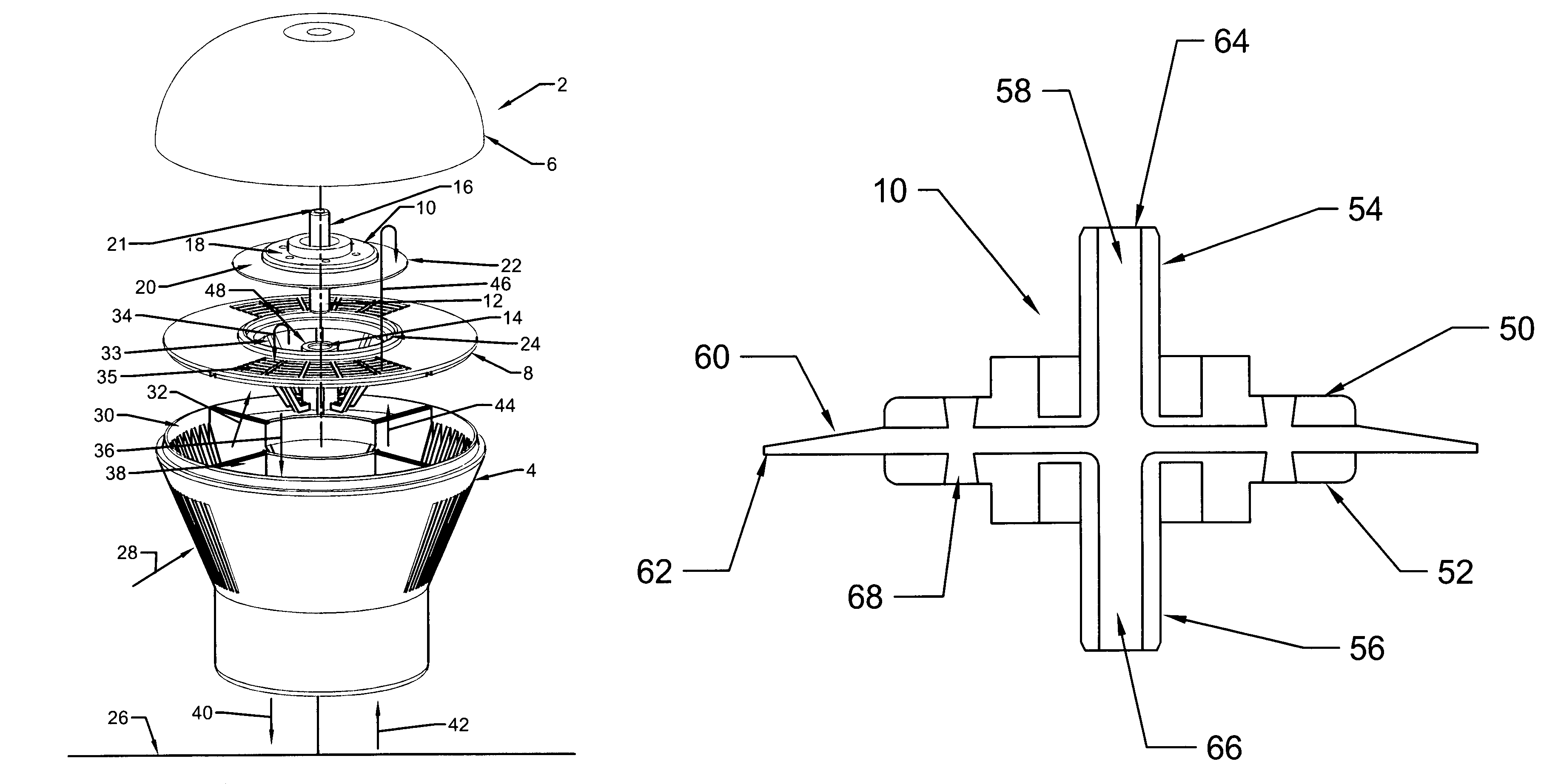
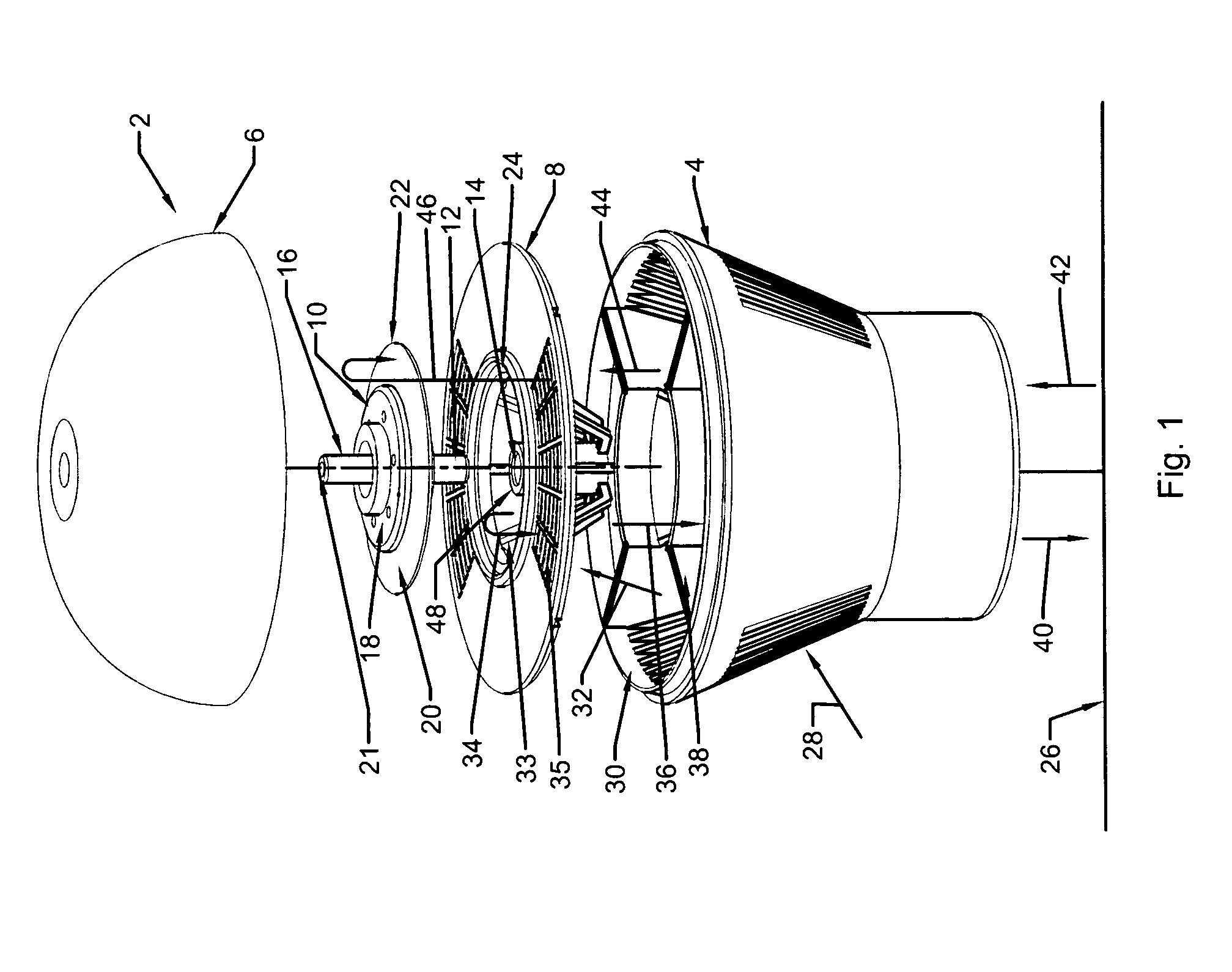
[0019]FIG. 1 is a perspective schematic diagram of an assembly of one embodiment of an air admittance valve. An air admittance valve 2 includes a base 4, a top 6 generally termed a “dome”, and a screen plate 8 coupled therebetween. The term “coupled,”“coupling,” and like terms are used broadly herein and can include any method or device for securing, binding, bonding, fastening, attaching, joining, inserting therein, forming thereon or therein, communicating, or otherwise associating, for example, mechanically, magnetically, electrically, chemically, directly or indirectly with intermediate elements, one or more pieces of members together and can further include integrally forming one functional member with another.

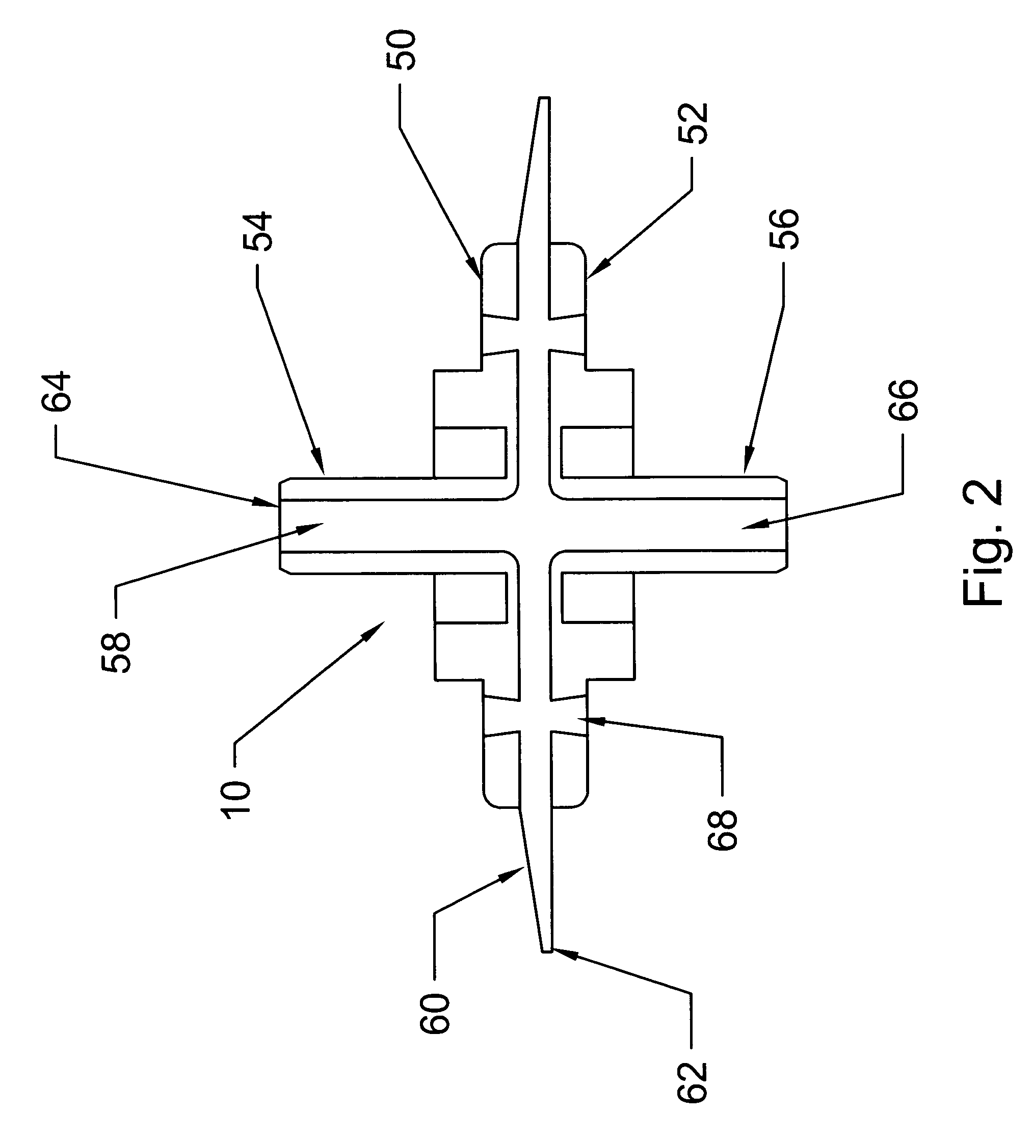
[0020]The screen plate 8 supports a diaphragm 10 that is operatively engaged with the screen plate. A central portion of the screen plate 8 forms a central opening 33 as a flow path for air entering the valve. The central opening 33 provides a sealing surface, herein a “s...


PUM

PropertyMeasurementUnit
Angleaaaaaaaaaa
Flow rateaaaaaaaaaa
Perimeteraaaaaaaaaa

Abstract

In some embodiments, an air admittance valve includes a base, a screen plate and a diaphragm engageable with the screen plate. The diaphragm may include a first center disk having a stem and a membrane coupled to the first center disk. The membrane may have a continuous material sized to extend beyond a perimeter of the first center disk, be formed of a material more pliable than the first center disk and be adapted to be coupled to the first center disk through the center disk stem.

Description

FIELD[0001]The invention relates to diaphragm valves. More specifically, the invention relates to diaphragm valves and related processes for sealing gaseous fluids.BACKGROUND[0002]Diaphragm valves are used in multiple industries. A particular type of diaphragm valve, known as an “air admittance valve,” is used in a wide variety of plumbing systems, such as apartments, schools, and single-family dwellings. For example, an air admittance valve can be installed on a plumbing system to seal unwanted gases escaping from the plumbing system, but allow air into the plumbing system to prevent negative pressure or a vacuum in the system.[0003]Thus, an air admittance valve functions as a special type of one-way valve to seal in one direction at relatively low pressures, but allow in another direction low pressure gas, such as atmospheric air, to pass around the diaphragm through the center of the valve. However, the valve is generally able to sustain a seal at elevated pressures. With these t...

Claims


Application Information

Patent Timeline
IPC IPC(8): F16K15/06E03F5/08
CPCE03C1/12F16K24/06F16K15/06E03C1/1225Y10T137/7897Y10T137/7917Y10T137/8122
Inventor GOHLKE, HENRY J.
Owner RECTORSEAL THE
Why Eureka
Try Eureka