Shock absorber with frequency-dependent damping

Inactive Publication Date: 2008-07-08
KONI BV
View PDF15 Cites 26 Cited by
  • Summary
  • Abstract
  • Description
  • Claims
  • Application Information

AI Technical Summary

Benefits of technology

[0019]Furthermore, it is possible to construct the valve seat/valve body with a variable first surface. That is to say the effective closing surface area of the valve body can be relatively large during a first portion of the closing movement and smaller during a secon

Problems solved by technology

Although they are effective, electronic controls of

Method used


Image

  • Shock absorber with frequency-dependent damping
  • Shock absorber with frequency-dependent damping
  • Shock absorber with frequency-dependent damping

Examples


Embodiment Construction

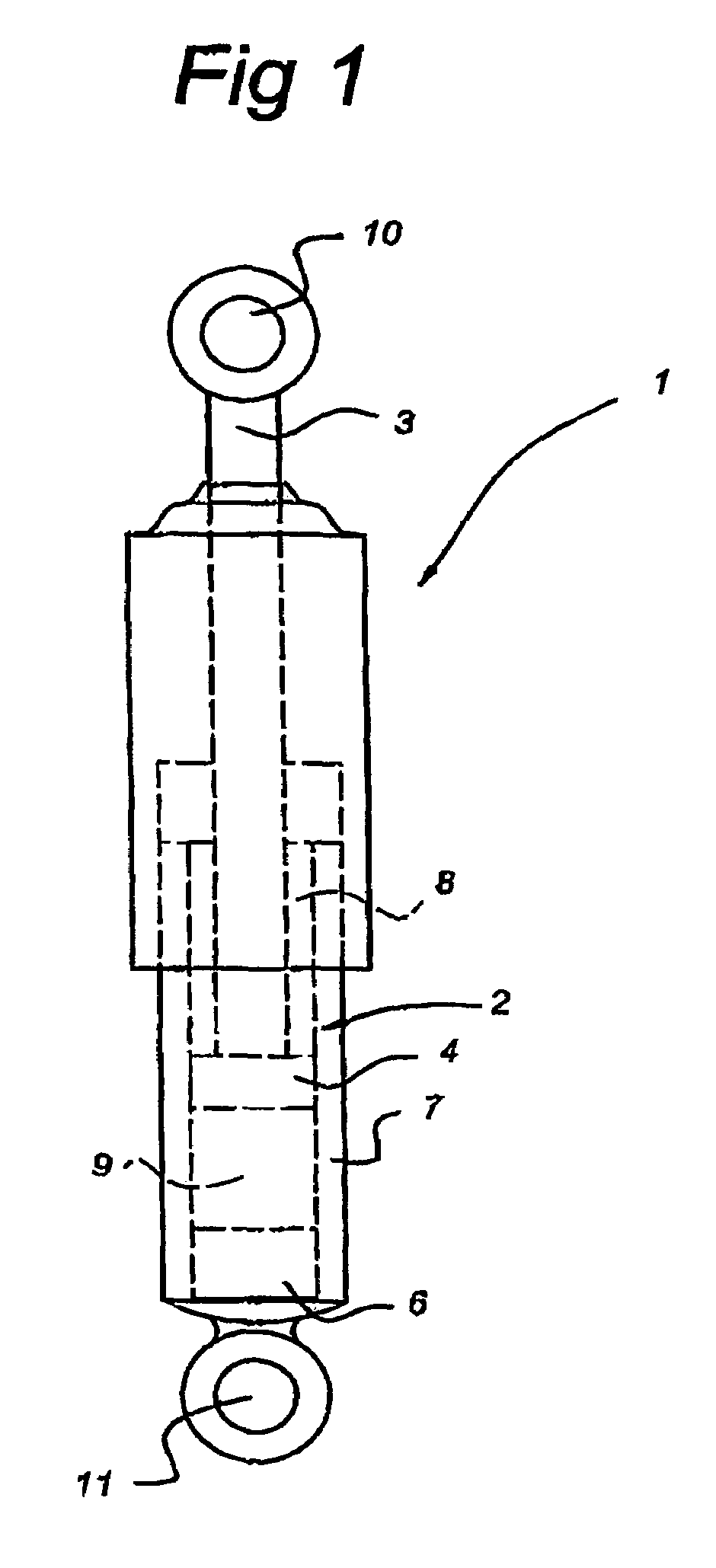
[0033]In FIG. 1 a shock absorber is indicated in its entirety by 1. This comprises a cylinder section 2 and a piston section 3. The piston section 3 comprises a piston 4 which delimits two chambers located opposite one another inside the cylinder section. A first chamber is indicated by 8 and a second chamber by 9. The piston section 3 can be fixed to, for example, vehicle bodywork through an eye 10. Eye 11 serves, for example, for fixing to part of the suspension system of a vehicle. The shock absorber shown here is of the type where the cylinder section 2 contains an annular channel 7 for storing absorber fluid and where there is a bottom valve 6 which connects second chamber 9 to this fluid reservoir 7. It must be understood that the invention can be employed with any type of absorber, in which content them may or may not be an external reservoir which can be constructed in some way known in the art.

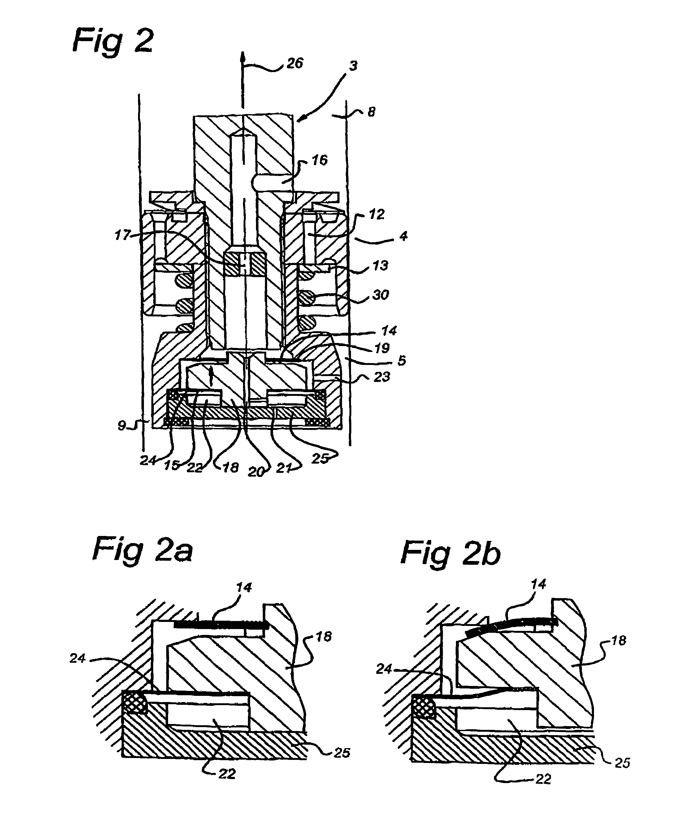
[0034]The construction of the piston section 3 in interaction with the cylinder s...


PUM


Abstract

Shock absorber containing a flow channel (16), provided with a valve assembly, made in the piston section. This valve assembly is designed to be actuated hydraulically. To this end there is an auxiliary chamber (22, 42) which on one side is eliminated by a movable valve body (18). This valve body is provided with an inlet for oil from the flow channel to the auxiliary chamber. There is an outlet (21, 41) (that can be closed off). The surface area of the valve body acting on the valve seat (19) is less than the surface area of the valve body in the auxiliary chamber, so that fluid flowing through the inlet of the valve body results in an increase in the volume of the auxiliary chamber and thus in closing movement of the valve body. Because filing of the auxiliary chamber takes some time, a frequenncy-dependend closing characteristic of the flow channel is obtained.

Description

BACKGROUND OF THE INVENTION[0001]The present invention relates to a shock absorber comprising a cylinder section and a piston section that van be moved therein, the piston section and cylinder section each being provided with fixings for connection with the parts that can be moved with respect to one another and said piston section being sealed with respect to said cylinder section in order to delimit chambers on either side thereof, a firsts chamber close to the fixing of said piston section and a second chamber close to the fixing of said cylinder section, a connecting channel being arranged between said chambers for connecting said chambers, said connecting channel containing a valve assembly for influencing the fluid steam through said connecting channel, comprising a valve seat and a part that can move with respect thereto under liquid pressure and seals off the valve seat, said movable part of the valve assembly forms a boundary wall of an auxiliary chamber, said auxiliary cha...

Claims


Application Information

Patent Timeline
IPC IPC(8): F16F9/34F16F9/46F16F9/512
CPCF16F9/512F16F2228/04Y10T137/88054
Inventor DE KOCK, PAULDE RUITER, ADRIANUS ANTONIUS WILHELMUS
Owner KONI BV
Why Eureka
Try Eureka