Blood drawing device with flash detection

a blood drawing device and flash detection technology, applied in the field of bodily fluid apparatus drawing, can solve the problems of undermining the integrity of the specimen, patient harm additionally, flash detection has been less than satisfactory in many such collection assemblies

Inactive Publication Date: 2008-07-08
CLEARVIEW PATIENT SAFETY TECH
View PDF103 Cites 59 Cited by
  • Summary
  • Abstract
  • Description
  • Claims
  • Application Information

AI Technical Summary

Problems solved by technology

If the needle tip is not in communication with the interior of the blood vessel during the procedure, the procedure is likely to be unsuccessful, causing error, undermining the integrity of the specimen, and the patient may be harmed additionally by the penetration of delicate underlying structures.
The observation of blood in the needle body is known as “flash.” Flash detection has been less than satisfactory for many such collection assemblies.
This delay can impede the determination of the precise moment at which the needle tip enters the blood vessel, which may cause the healthcare worker inserting the needle to miss or perforate the vessel and penetrate into delicate surrounding structures.
In other instances, while flash occurs, the visual indication of flash is not easily detected because the amount of flash is small or obscured due to the positioning of the collection assembly.

Method used


Image

  • Blood drawing device with flash detection
  • Blood drawing device with flash detection
  • Blood drawing device with flash detection

Examples


first embodiment

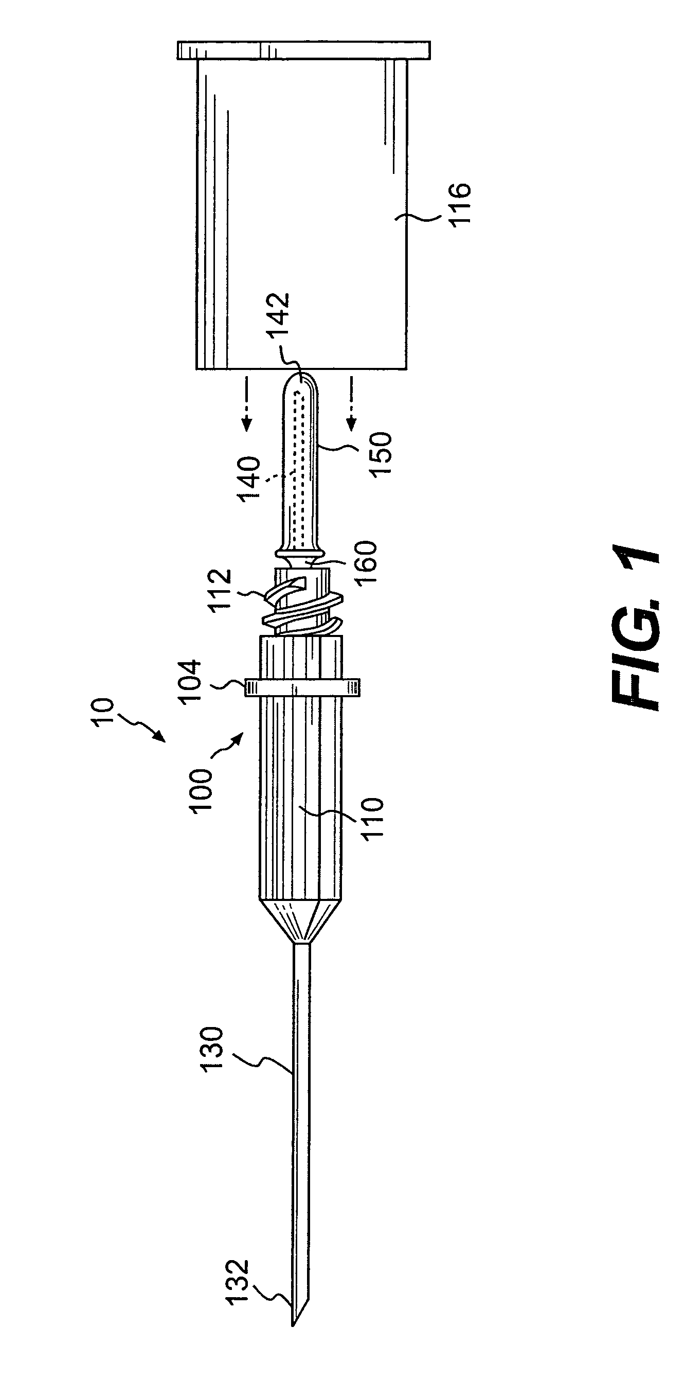
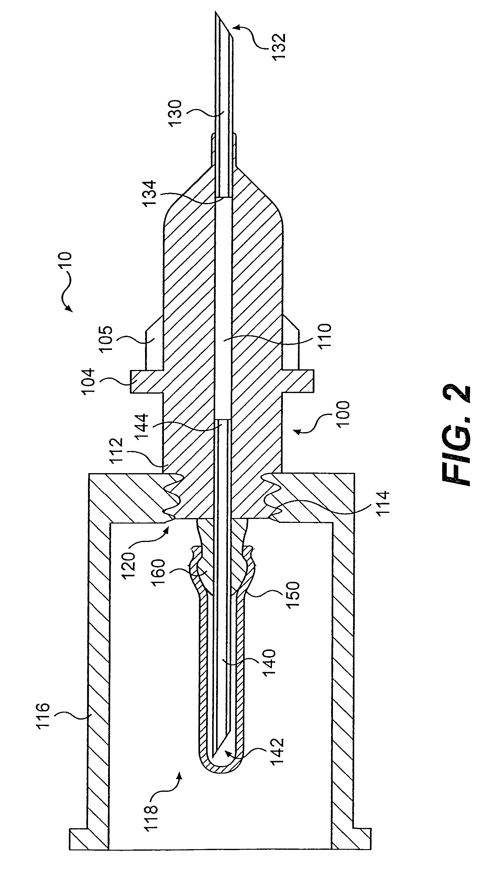
[0023]Reference will now be made in detail to the present invention, an example of which is illustrated in the accompanying drawings. With reference to FIG. 1, an exploded pictorial view of a blood-drawing device 10 is shown. The blood-drawing device 10 includes a front cannula 130, a central body 100, a venting member 160, a rear cannula 140, and a flexible sleeve 150. A guide tube 116 may be connected to the central body 100. The front cannula 130 and the rear cannula 140 may each have a generally elongated cylindrical body defining an elongated fluid passage extending from one end of the cannula to the other end. The front cannula 130 may extend from the front end of the central body 100 and terminate at a tapered or pointed end 132, which is adapted to be inserted into a lumen. The rear cannula 140 may extend from the rear of the central body 100 and terminate at a tapered or pointed end 142. The sleeve 150 may isolate the rear cannula 140 from the ambient, wherein the ambient i...

second embodiment

[0034]the present invention is shown in an exploded side view in FIG. 5A. With reference to FIG. 5A, a Luer-type blood-drawing device is provided with a venting member 160. The central body 100 may be provided with an enlarged fluid passage 110 which may improve flash visibility. It is appreciated that the enlarged fluid passage could have any of a number of different shapes and sizes, which may be uniform or non-uniform over the length of the passage. It is further appreciated that the fluid passage 110 in each embodiment of the invention described herein, could have any of a variety of shapes and sizes without departing from the intended scope of the invention.

[0035]The butterfly needle 180 may be connected to the Luer-type hub 102 via a butterfly connection tube 182. The butterfly needle 180 may include a butterfly (i.e., front) cannula 184 and one or more wings 186. The butterfly cannula 184 may be inserted directly into the body lumen for blood collection. Flash may be observed...

third embodiment

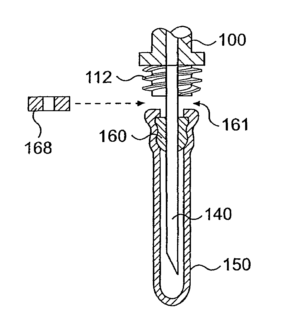
[0041]the present invention is shown in FIG. 6. With reference to FIG. 6, a porous member 160 may be inserted over the rear cannula 140 and slightly separated from the rear portion of the central body 100 (i.e., the portion proximate to the rear cannula 140), leaving a small space 161 between the central body and the porous member. The porous member 160, itself, and / or the seal it forms against the rear cannula, may not completely prevent blood from escaping past the porous member. In such instances, the porous member 160 may be constructed of material that is porous to gas (air) and somewhat, but not perfectly, non-porous to blood. The porous member 160 may preferably include a tapered portion, however, it is appreciated that the porous member may have any alternative shape, such as cylindrical, spherical, irregular, or the like, without departing from the intended scope of the invention.

[0042]In embodiments in which the porous member 160 is not completely non-porous to blood, a ga...


PUM


Abstract

A device for drawing fluid from a lumen, and particularly blood from a blood vessel, is disclosed. The device may provide indication of the entry of an intravenous cannula into the lumen. The device may include a central body having an outer wall and an inner fluid passage. The device may include a luer-type adapter to permit the attachment of an I.V. infusion set of various lengths (“butterfly needle”) and or any luer-type fitting attached to an existing device. The outer wall of the central body may be transparent or translucent to permit the detection of fluid within the inner fluid passage. A front cannula may extend from one end of the central body and a rear cannula may extend from the other end of the central body. Both the front and rear cannulae may communicate with the inner fluid passage. A transparent or translucent flexible sleeve may surround at least a tip portion of the rear cannula. A venting member may be provided near a base portion of the rear cannula between the flexible sleeve and the ambient. The venting member may permit the passage of air through it, but be substantially impermeable to liquids, such as blood.

Description

FIELD OF THE INVENTION[0001]The present invention relates to an apparatus for drawing bodily fluids, and particularly blood, from an animal.BACKGROUND OF THE INVENTION[0002]Intravenous blood collection assemblies have long been used to draw bodily fluids, such as blood, from patients. With respect to drawing blood in particular, the vessel or lumen from which the blood is drawn is often rather small and or not visible. If the needle tip is not in communication with the interior of the blood vessel during the procedure, the procedure is likely to be unsuccessful, causing error, undermining the integrity of the specimen, and the patient may be harmed additionally by the penetration of delicate underlying structures. Accordingly, confirmation of accurate placement of the needle tip into a blood vessel is desirable for blood drawing procedures.[0003]Past intravenous blood collection assemblies have included mechanisms for indicating when a needle tip is in communication with the interio...

Claims


Application Information

Patent Timeline
Patent Type & Authority Patents(United States)
IPC IPC(8): A61M1/00A61B5/00B65D81/00A61B5/15A61B5/155A61M25/00A61M25/06
CPCA61B5/1427A61B5/1444A61M25/0693A61B5/15003A61B5/150213A61B5/150351A61B5/150389A61B5/150473A61B5/150572A61B5/150732A61B5/15074A61B5/1545
Inventor BROWN, LEROY
Owner CLEARVIEW PATIENT SAFETY TECH
Why Eureka
Try Eureka