
Fluid coupling

a technology of fluid coupling and fluid, which is applied in the field of fluid coupling, can solve the problems of unacceptable variations in flow rate, abnormalities in the intended administration of fluid to the patient, and the fabrication of v-set fluid coupling can be a bit time-consuming, so as to facilitate attachment and detachment.

Pending Publication Date: 2021-07-08
PALMAYA
View PDF0 Cites 0 Cited by
  • Summary
  • Abstract
  • Description
  • Claims
  • Application Information

AI Technical Summary

Benefits of technology

The patent describes a connector that allows multiple fluid tubes to be connected together without mixing them. The connector has a male luer connector that can be attached to a female luer connector. Each tube has a valve or coupling element for easy attachment and detachment of fluid sources and ancillary components. This design allows for continuous flow of fluid within the body and ensures the fluid is not mixed with other fluids.

Problems solved by technology

Some such proposals have, however, proved to be problematic, as a result of causing unacceptable variations in the flow rates of the different fluids.
The existence of a relatively large common space in which prior mixing of the fluids occurs may result one of the fluids affecting the flow rate of another fluid, leading to abnormalities in the intended administration of the fluid to the patient.
While the V-set fluid coupling disclosed in WO 91 / 10861 has proved to be a commercial success, it has certain deficiencies.
Firstly, the V-set fluid coupling can be somewhat time consuming to fabricate.
Further, this process of fabrication may bring about certain deficiencies in operation of the V-set as a fluid coupling.
In particular, it is likely that the end section of each tube would have experienced some stretching in the process of being fed into the cavity, leading to a reduction the cross-section flow area of the lumen and thus restricting flow.
Furthermore, there are space constraints arising from the need to feed a plurality of tubes through a single cavity and have sufficient space remaining to receive the adhesive or resin.
Because of these space constraints, there are limitations regarding the cross-sectional size of tube that can be used to fabricate the V-set fluid coupling.

Method used


Image

  • Fluid coupling
  • Fluid coupling
  • Fluid coupling

Examples


Embodiment Construction

[0059]In the following detailed description, the present invention is described in connection with several preferred embodiments. However, to the extent that the following description is specific to particular embodiments or a particular use of the present techniques, it is intended to be illustrative only and merely provides a concise description of the exemplary embodiment. Accordingly, the present invention is not limited to the specific embodiments described below, but rather the invention includes all alternatives, modifications, and equivalents falling within the true scope of the appended claims.

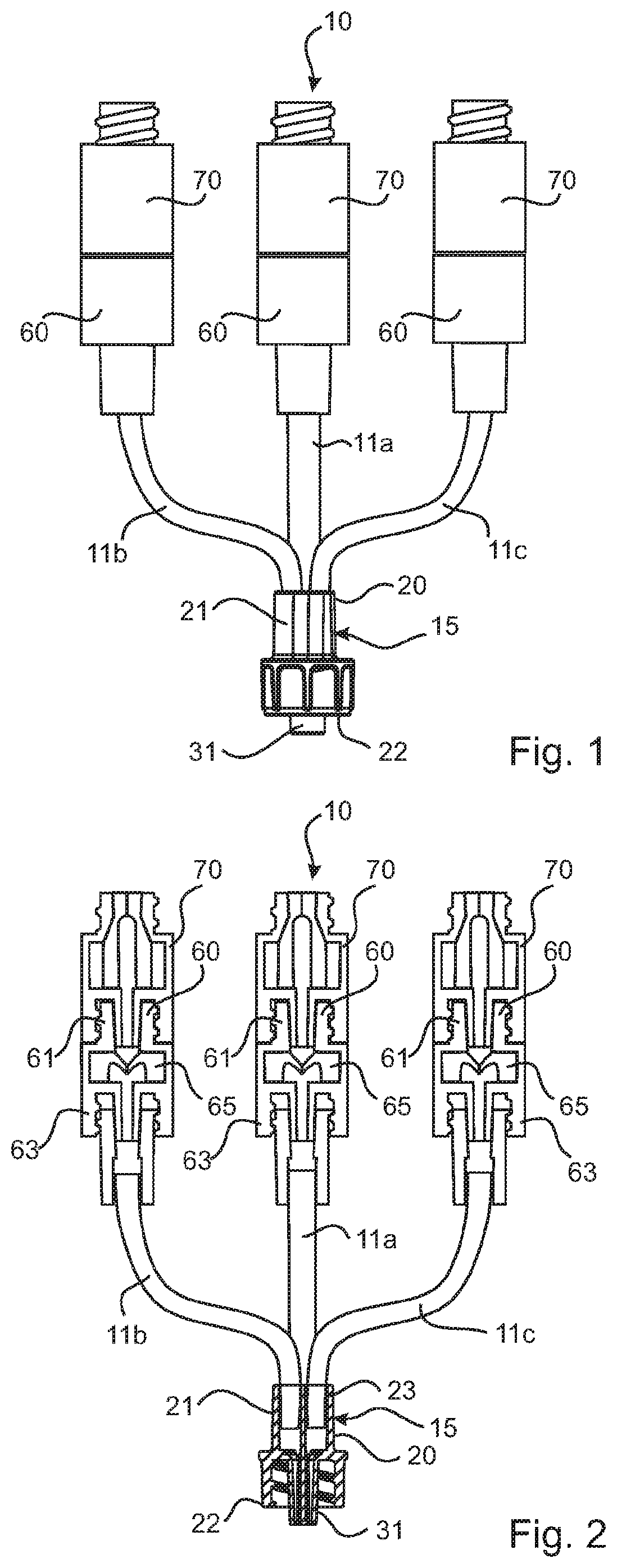
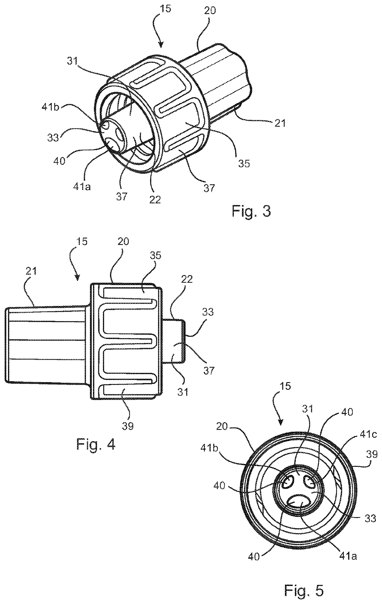
[0060]The embodiments will be described with reference to a fluid coupling 10 for joining several intravenous fluid delivery tubes 11 to a single-bore outlet member in the form of an intravenous cannula (not shown). There are at least two tubes 11, as will be discussed further later.

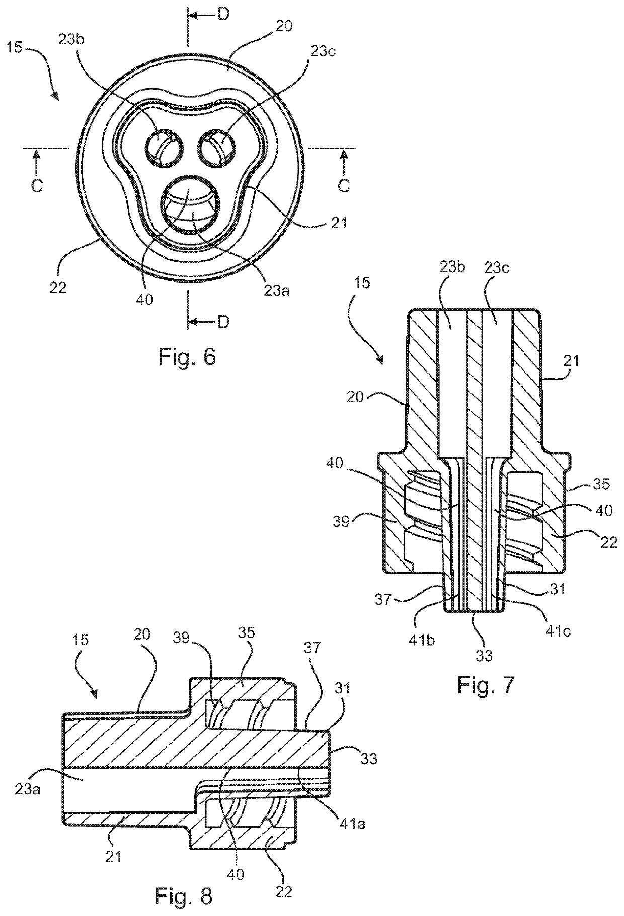
[0061]Referring to FIGS. 1 to 11, a first embodiment of the fluid coupling 10 comprises three fluid del...


PUM


Abstract

A fluid coupling (10) comprising several intravenous fluid delivery tubes (11) and a connector (15). The connector (15) is configured for attachment to an intravenous cannula or needle. The connector (15) comprises a body (20) having a first end portion (21) and a second end portion (22). The first end portion (21) comprises a plurality of sockets (23), each socket being adapted to receive an end section of a respective fluid delivery tube (11). The second end portion (22) comprises a nozzle (31) having an end face (33), wherein there is a plurality of interior flow paths (41) within the nozzle. Each flow path (41) opens onto the end of the nozzle (31) and communicates with a respective one of the sockets (23), whereby fluid delivered by each tube (11) is transported along the respective flow path (41) to the end of the nozzle (31) and the intravenous cannula or needle attached thereto. Each tube (11) has an end section thereof sealingly received in a respective socket (23).

Description

TECHNICAL FIELD[0001]This invention relates to a fluid coupling for connecting a plurality of fluid sources to an outlet member, and to a connector for use as part of a fluid coupling.[0002]The invention is particularly applicable as a coupling for joining several intravenous fluid delivery tubes to a single-bore outlet member (such as an intravenous cannula or needle). Accordingly, it will be convenient to hereinafter disclose the invention in relation to that exemplary application. However, it is to be appreciated that the invention is not limited to that application and may be used in other applications requiring connection of a plurality of fluid sources to a single-bore outlet member of some form.BACKGROUND ART[0003]The following discussion of the background art is intended to facilitate an understanding of the present invention only. The discussion is not an acknowledgement or admission that any of the material referred to is or was part of the common general knowledge as at t...

Claims


Application Information

Patent Timeline
IPC IPC(8): A61M39/10
CPCA61M39/105A61M2039/242A61M2039/1077F16L39/02A61M2039/1016A61M2039/1033A61M2039/1066A61M2039/1083A61M2205/02A61M2205/75A61M2039/0027
Inventor O'NEIL, ALEXANDER GEORGE BRIAN
Owner PALMAYA
Learn More