
Intravenous cannula

a cannula and intravenous technology, applied in the field of medical devices, can solve the problems of blood spillage, unhygienic conditions for patients, and the risk of infection of healthcare workers, and achieve the effect of reducing the risk of infection for healthcare workers and reducing the risk of infection

Pending Publication Date: 2022-08-11
MEDSOURCE INT LLC
View PDF0 Cites 0 Cited by
  • Summary
  • Abstract
  • Description
  • Claims
  • Application Information

AI Technical Summary

Benefits of technology

The patent text describes a catheter device with a valve closure member and a needle guard assembly. The valve closure member is placed in the catheter hub and has two surfaces that seal the fluid passage. The needle guard assembly has a body and a safety clip that locks onto the catheter hub and prevents accidental needle prick injuries. The catheter device also includes a curved protrusion that guides the needle member and prevents misalignment during withdrawal. The needle member is designed with a protuberance that engages with a bracket to ensure the needle member cannot be easily retrived from the needle guard assembly. These features improve the safety and functionality of the catheter device.

Problems solved by technology

One drawback associated with the use of over-needle intravenous cannulas is that once the needle is withdrawn from the cannula, there is an open channel for the blood to flow through the cannula and spill out of a catheter hub.
The blood may be contaminated and this may lead to risk of infection for the healthcare worker.
Additionally, spillage of blood leads to unhygienic conditions for the patient as well as in the healthcare space where the catheter is applied.
Blood spillage is currently a major problem during administration of IV catheters.
Additionally, over-needle cannulas that provide protection to a user from a “needle stick” or “needle prick” injuries is not yet prevalent.
The risks associated with such “needle prick” injuries are high because of the high prevalence of communicable diseases among patients in hospitals and especially in emergency rooms where cannulation treatment must be initiated immediately.
Also, the costs associated with any complication or adverse effects associated with such “needle prick” injuries are very high.
There are known methods to avoid blood spillage, however these methods are associated with certain risks and drawbacks.
In either case, the flow of blood still cannot be stopped.
However, these products are bulky, complicated to use, and more expensive.
In yet another known method, the catheter space may be blocked by a mandrel or obturator which requires proper skill and training and that further makes the product complicated in structure and to operate, and is expensive.
However, these catheter introducer devices require additional training for the user to operate.
Also, the needle catheter assembly is not robust, as the user remains in contact with the needle tip cover and in case the needle cover tip is manipulated by the user during application, the user may get exposed to the needle tip and thus the risk of injuries to the user while operating the catheter introducer assembly is high.
Also, manufacturing of such needle catheter assemblies is complex and not cost effective.
One of the problems associated with the device disclosed in Pat '3031 is that when the needle is retracted from the needle cover, the needle cover does not disengage from the catheter hub, and more force is required to disengage the needle cover from the catheter hub.
Another problem associated with the needle disclosed in Pat '3031 is that the needle does not engage the needle cover with the catheter hub, which affects the functionality of the catheter.
This may lead to manipulation of the catheter device by the operator to extract the needle cover from the hub, which in turn may disturb and damage the vein, thereby causing pain to the patient.
In addition to the above limitations and associated problems, the existing devices having leaf springs, for example as disclosed in Pat '3031, face problems related to improper guiding of the needle tip inside the catheter hub when the needle is inserted through the leaf spring.
This may lead to blunting of needle tip when the needle tip contacts the other parts of the safety pin or the catheter hub when operated to move into the catheter hub.

Method used


Image

  • Intravenous cannula
  • Intravenous cannula
  • Intravenous cannula

Examples


Embodiment Construction

[0039]Provided below is a non-limiting exemplary embodiment of the present invention. Reference will now be made in detail to specific embodiments or features, examples of which are illustrated in the accompanying drawings. Wherever possible, corresponding or similar reference numbers will be used throughout the drawings to refer to the same or corresponding parts. Moreover, references to various elements described herein are made collectively or individually when there may be more than one element of the same type. However, such references are merely exemplary in nature. It may be noted that any reference to elements in the singular may also be construed to relate to the plural and vice-versa without limiting the scope of the disclosure to the exact number or type of such elements unless set forth explicitly in the appended claim(s).

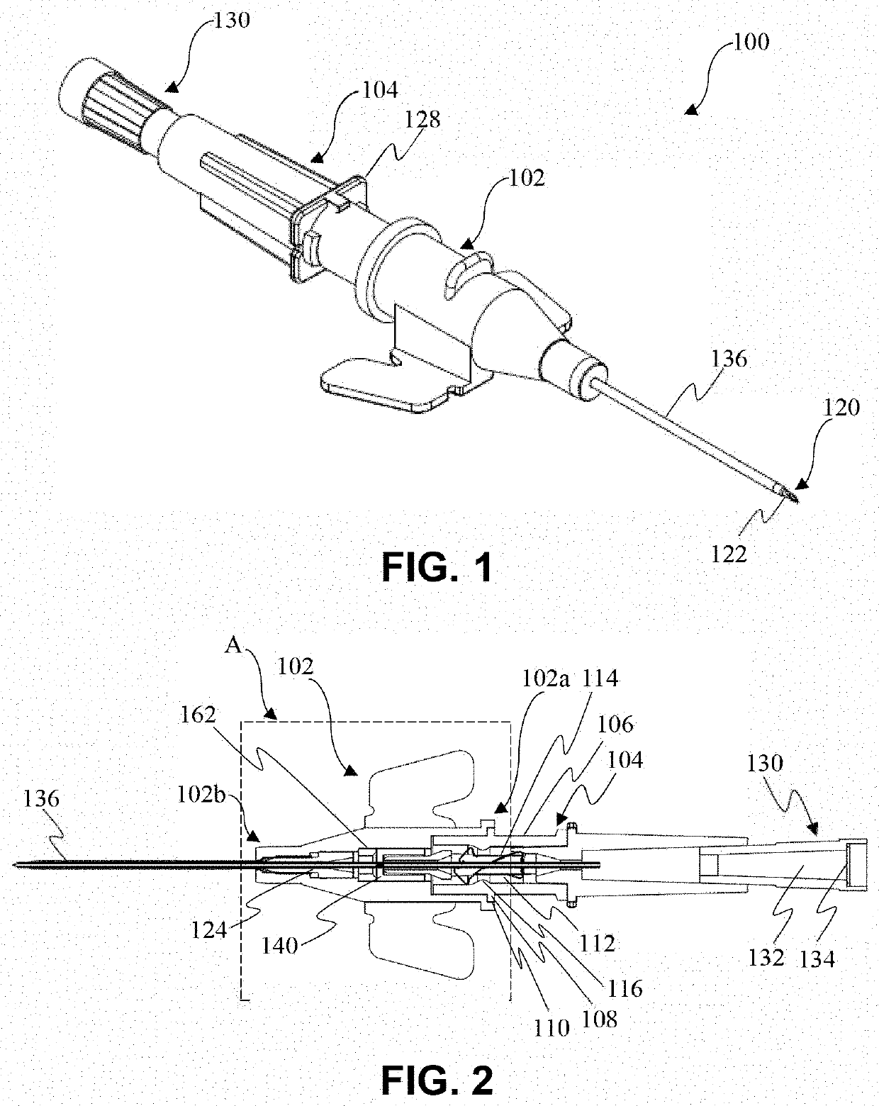
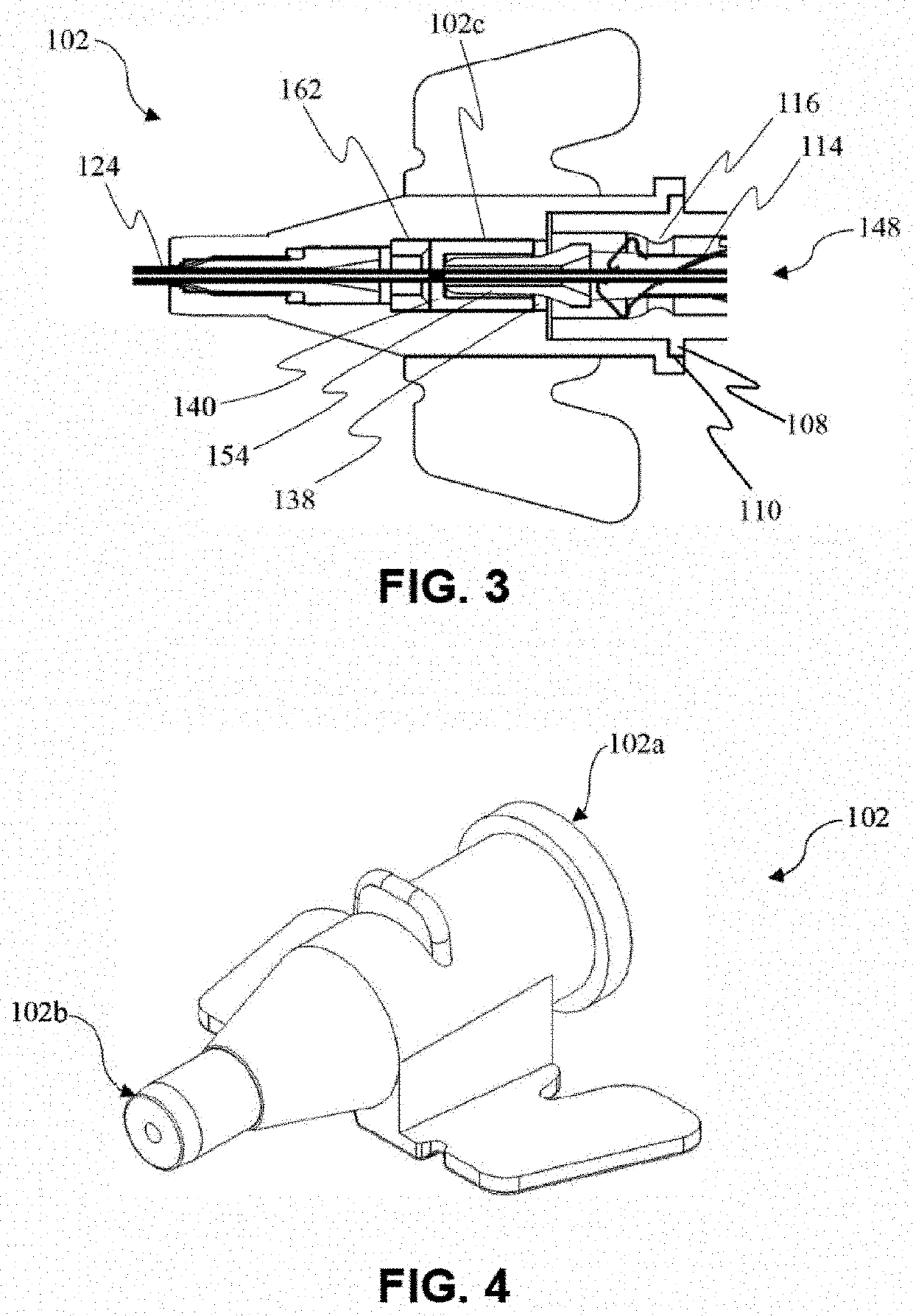
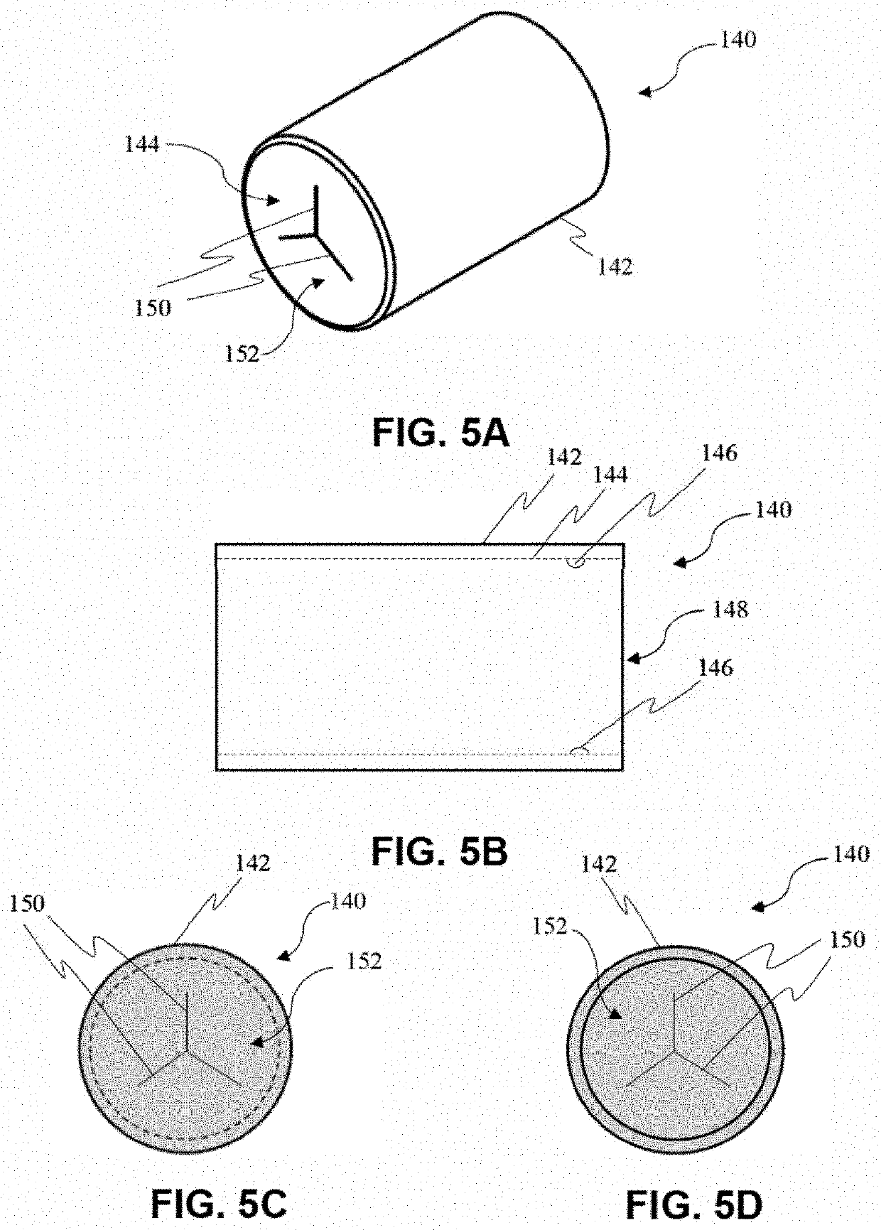
[0040]FIGS. 1 and 2 are perspective and sectional views of a cannula (100) according to an exemplary embodiment of the present disclosure. The cannula ...


PUM


Abstract

The present disclosure discloses an intravenous cannula that includes a catheter hub and tubular valve member adapted to allow a needle member to pass through. The valve member is defined with slits that allow the needle to pass through. Further, a valve closure member and needle guard assembly are provided, both adapted to close passage for fluid flow and prevent blood flow from the punctured vein of a subject. The needle guard assembly includes a body portion. A safety clip locks onto a flange defined in the body, and in a biased condition allows a needle to extend through the body and hub. Upon withdrawal of the needle from a proximal end of the hub, a safety pin disengages from the flange and arrests the tip portion of the needle within the device, thereby preventing needle prick injury upon withdrawal of the needle member from the hub.

Description

CROSS-REFERENCE TO RELATED APPLICATION[0001]This patent application claims the priority of Indian patent application number 202111005687, filed Feb. 10, 2021 entitled “Intravenous Cannula,” the disclosure content of which is hereby incorporated by reference.TECHNICAL FIELD[0002]The present disclosure relates to medical devices. More particularly, the disclosure relates to intravenous cannulas configured to prevent backflow of blood and needle prick injuries.BACKGROUND OF THE DISCLOSURE[0003]Intravenous (IV) cannulas have been in existence for many years. Intravenous cannulas are venous devices used to infuse medication or fluids directly into a vein or draw blood samples for testing. Intravenous cannulas are introduced into a vein using a needle and fixed to the patient's skin with an adhesive tape.[0004]One drawback associated with the use of over-needle intravenous cannulas is that once the needle is withdrawn from the cannula, there is an open channel for the blood to flow throug...

Claims


Application Information

Patent Timeline
Patent Type & Authority Applications(United States)
IPC IPC(8): A61M25/06A61M25/00
CPCA61M25/0618A61M25/0097A61M25/0637
Inventor GUPTA, NEERAJ
Owner MEDSOURCE INT LLC
Learn More