Intravenous cannula assembly

a cannula and assembly technology, applied in the field of intravenous cannula assemblies, can solve the problems of relative clumsy procedures, risk of spreading blood-borne diseases, and medical practitioners/other personnel being infected

Inactive Publication Date: 2011-05-26
WALSH ALLAN +1
View PDF5 Cites 0 Cited by
  • Summary
  • Abstract
  • Description
  • Claims
  • Application Information

AI Technical Summary

Benefits of technology

a co-operating structure of said barrel adapted to engage said tabs, deflecting said tabs inwardly, as said cannula guard is deployed toward said deployed position, and to engage a trailing end of each said tab when said cannula guard is in said deployed position, preventing displacement of said cannula guard from said deployed position toward said retracted position.

Problems solved by technology

Whilst the cover located on the tube is intended to be slipped down over the needle for protection, this is a relative clumsy procedure.
Prior to successfully covering the needle, there is a risk of spreading blood-borne diseases.
The medical practitioner or other personnel involved in processing the collected blood may inadvertently prick themselves with the needle or wipe blood on the exterior of the needle onto their skin.
If the donor's blood is infected, the medical practitioner / other personnel may become infected.
Conversely, if the medical practitioner / other personnel is carrying a blood-borne disease, the collected blood may become infected.
Similar risks exist in other types of intravenous cannula assembly applications.

Method used


Image

  • Intravenous cannula assembly
  • Intravenous cannula assembly
  • Intravenous cannula assembly

Examples


first embodiment

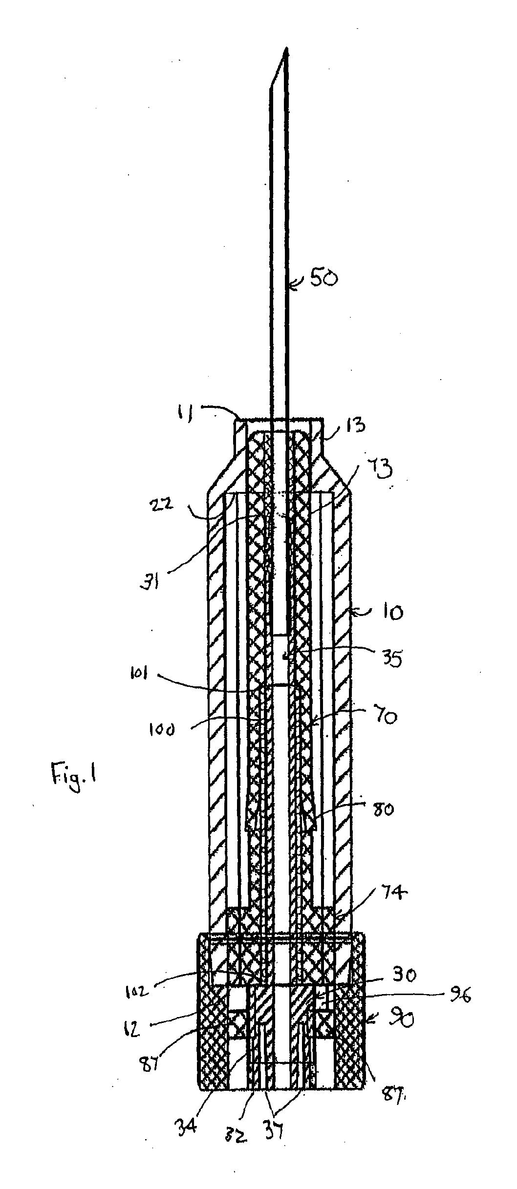
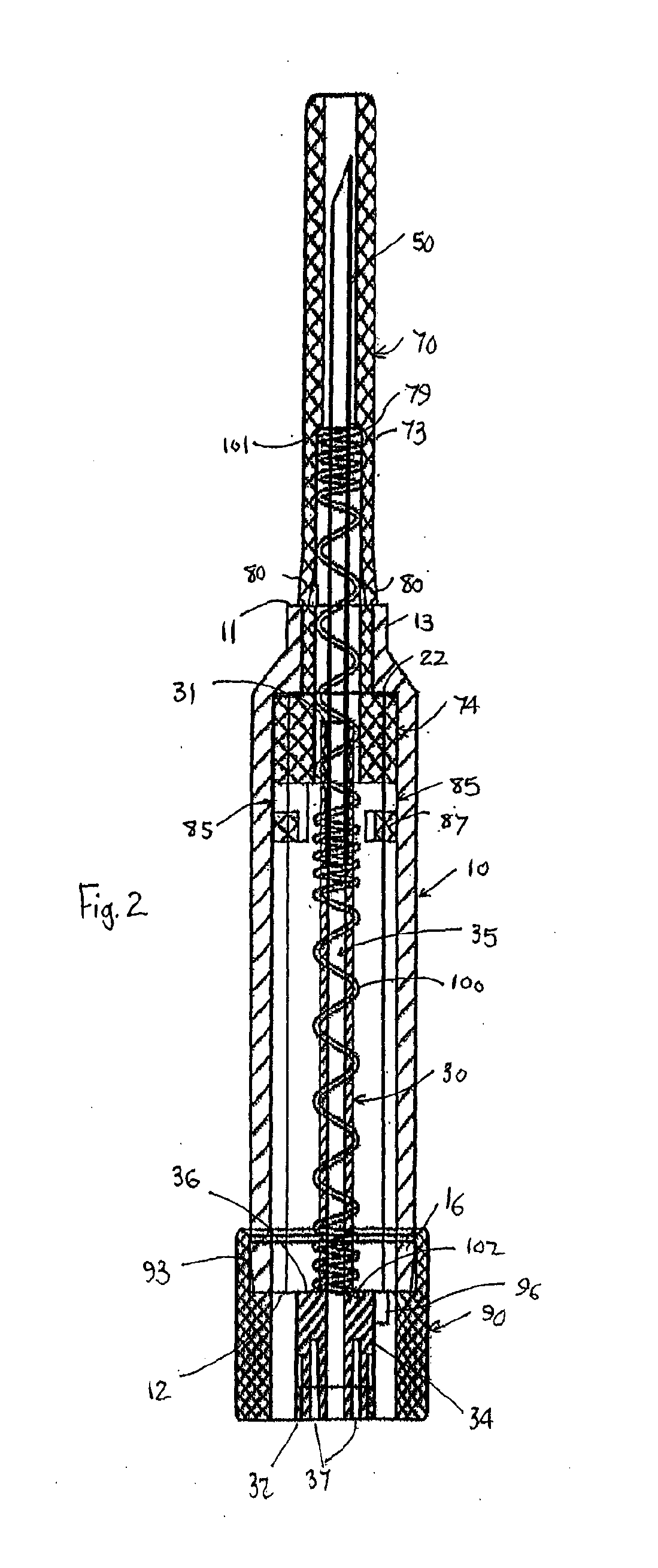
Referring firstly to FIGS. 1 and 2 of the accompanying drawings, an intravenous cannula assembly 1 in the form of a blood bag needle assembly, generally comprises a barrel 10, cannula hub 30, cannula 50, cannula guard 70 and deployment mechanism which here includes a locking member 90 and spring 100. The barrel 10 has a barrel leading end 11 and a barrel trailing end 12. The cannula hub 30 has a hub leading end 31, a hub trailing end 32 and a hub aperture 35 extending therebetween. The cannula 50, here in the form of a blood bag needle, is mounted in, and in fluid communication with, the hub aperture 35 and extends from the hub leading end 31 through the barrel leading end 11. The cannula guard 70 is concentrically mounted about the cannula hub 30. The deployment mechanism is operable to deploy the cannula guard 70 from a retracted position, depicted in FIG. 1, at which it is at least substantially located within the barrel 10, to a deployed position, depicted in FIG. 2, extending ...

second embodiment

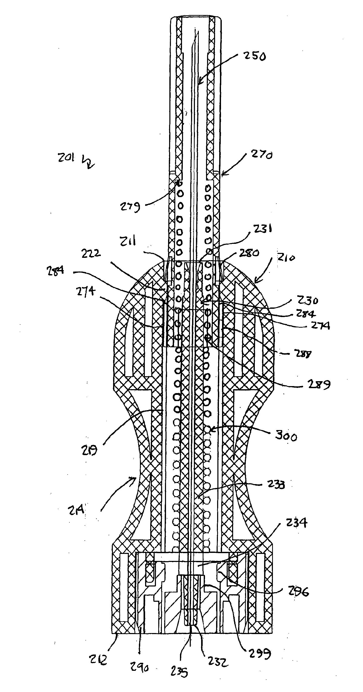
The cannula hub 230 of the second embodiment is depicted in detail in FIGS. 27 and 28. The cannula hub 230 comprises an elongate tubular hub stem 233 located towards the hub leading end 231 and a flattened hub boss 234 located towards the hub trailing end 232. A pair of opposing shoulders 236 are defined by the leading face of the flattened hub boss 234 were it meets the trailing end of the hub stem 233. A tapered tubular hub tail 237 extends between the flattened hub boss 234 and hub trailing end 232. The hub tail 237 has a tapered exterior diameter sized to receive a blood delivery tube (not depicted) such that the blood delivery tube is in fluid communication with the hub aperture 235 that extends through the length of the cannula hub 230. The hub aperture 235 is sized to receive the cannula / needle 250 at the hub leading end 231 with an interference fit so that the needle 250 remains fixed in relation to the cannula hub 230.

The cannula guard 270 of the second embodiment is depict...


PUM


Abstract

An intravenous cannula assembly comprises a longitudinally extending barrel (10, 210), a cannula hub (30, 230), a cannula (50, 250), a cannula guard (70, 270) and a deployment mechanism (90, 100, 290, 300). The cannula hub (30, 230) is mounted in the barrel (10, 210) and has a hub aperture (35, 235) extending between the hub leading end (31, 231) and hub trailing end (32, 232). The cannula hub (30, 230) is adapted to mount a tube at the hub trailing end (32, 232) in fluid communication with the hub aperture (35, 235). The cannula (50, 250) is mounted in, and in fluid communication with, the hub aperture (35, 235). The cannula (50, 250) extends from the hub leading end (31, 231) through the barrel leading end (11, 211). The cannula guard (70, 270) is concentrically mounted about the cannula hub (30, 230). The deployment mechanism (90, 100, 290, 300) is adapted to deploy the cannula guard (70, 270) from a retracted position substantially within the barrel (10, 210) to a deployed position extending from the barrel leading end (11, 211) and covering the portion of the cannula (50, 250) extending through the barrel leading end (11, 211).

Description

TECHNICAL FIELDThe present invention relates to the field of intravenous cannula assemblies and in particular relates to, but is not limited to, a blood bag needle assembly.BACKGROUND OF THE INVENTIONTypical blood bag systems for use in extracting blood from blood donors consist of a blood bag for storing the extracted blood, a flexible delivery tube fixed at one end to (and communicating with) the blood bag and a needle fixed to (and communicating with) the opposing end of the delivery tube. A needle cap is mounted on the needle and a needle cover is typically loosely mounted on the tube. In use, the medical practitioner firstly removes the needle cap so as to expose the needle. The needle is inserted into the donor's arm and blood extracted from the donor into the blood bag via the delivery tube. Once the blood extraction is complete, the delivery tube is clamped and the needle is removed from the donor's arm. The removed needle bears the donor's blood and freely dangles at the en...

Claims


Application Information

Patent Timeline
Patent Type & Authority Applications(United States)
IPC IPC(8): A61B5/15
CPCA61M25/0631A61M5/326
Inventor WALSH, ALLANTAN, FEIYAN
Owner WALSH ALLAN
Why Eureka
Try Eureka