Infusion device and driving mechanism for same

a technology of driving mechanism and infusion device, which is applied in the direction of process and machine control, other medical devices, instruments, etc., can solve the problems of simple dumping of devices and replacement of batteries, and achieve the effect of reducing the thickness form factor of the drive mechanism, reducing the thickness form factor, and reducing the thickness of the drive mechanism

Inactive Publication Date: 2008-07-08
MEDTRONIC MIMIMED INC
View PDF20 Cites 189 Cited by
  • Summary
  • Abstract
  • Description
  • Claims
  • Application Information

AI Technical Summary

Benefits of technology

[0007]Preferred embodiments of the invention relate to such devices and drive mechanisms configured for implantation in a patient's body. Configurations described herein allow the drive mechanism and, thus, the infusion device to have a relatively small thickness dimension, for example, to minimize trauma to the implant recipient (referred to herein as the patient).
[0012]The infusion device further includes a drive mechanism having an inlet coupled in fluid flow communication with the reservoir and an outlet coupled in fluid flow communication with the infusion device housing outlet. In one embodiment, a filter may be disposed between the reservoir and the drive mechanism (or as part of the inlet of the drive mechanism). In a further embodiment, expandable and compressable devices, such as one or more volume compensators or accumulators, which may also be, for example, accumulators, also may be disposed in the flow path between the reservoir and the drive mechanism inlet, to dampen surges and ebbs in the flow.
[0015]Embodiments of the invention employ a coaxial arrangement of the piston, the piston channel and the coil, to provide significant advantages with respect to providing a relatively thin form factor and efficient power usage. A number of features can each provide or be combined to contribute to a reduction in the thickness form factor of the drive mechanism. For example, a coaxial arrangement of components can be implemented with a smaller thickness form factor than alternative arrangements in which components are arranged in series with each other in the thickness dimension. Embodiments may include an inlet volume on one side of the coil and an outlet chamber on the opposite side of the coil, with a flow passage through the piston channel, such that the coil and flow channel share a common portion of the thickness dimension. The armature may be located within the inlet volume and, thus, share a common portion of the thickness dimension with the inlet volume. The outlet chamber may be centrally located within the same housing that has the coil cup and formed in relatively close proximity to the coil cup in the thickness dimension of the housing.
[0017]In addition, a number of features described herein can provide, or be combined to contribute to, the efficient use of power to, prolong the operational life of the drive mechanism. One manner of improving the operational life of an infusion device according to embodiments of the present invention, is to lower the power consumption requirements of the drive mechanism by employing a coaxial coil and piston configuration and one or more features for making highly efficient use of electromagnetic energy. Another manner of improving the operational life of a device according to embodiments of the invention is to reduce the number of operations of the drive mechanism required over a given period of time, by pumping reduced volumes of a higher concentration infusion medium (an infusion medium with a higher concentration of active ingredients) or pumping higher concentration volumes at reduced intervals.

Problems solved by technology

In some devices, when the batteries die, the devices are simply thrown away.
Also, as the battery power supplies for such devices have limited capacities, some devices typically require multiple replacements of batteries over their operational life.

Method used


Image

  • Infusion device and driving mechanism for same
  • Infusion device and driving mechanism for same
  • Infusion device and driving mechanism for same

Examples


Embodiment Construction

[0045]The following detailed description is of the best presently contemplated mode of implementing the invention. This description is not to be taken in a limiting sense, but is made merely for the purpose of illustrating the general principles of embodiments of the invention. The scope of the invention is best defined by the appended claims.

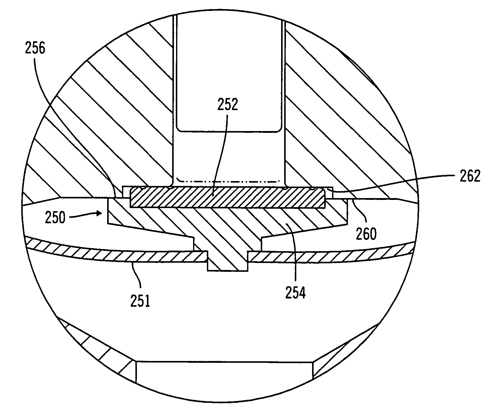
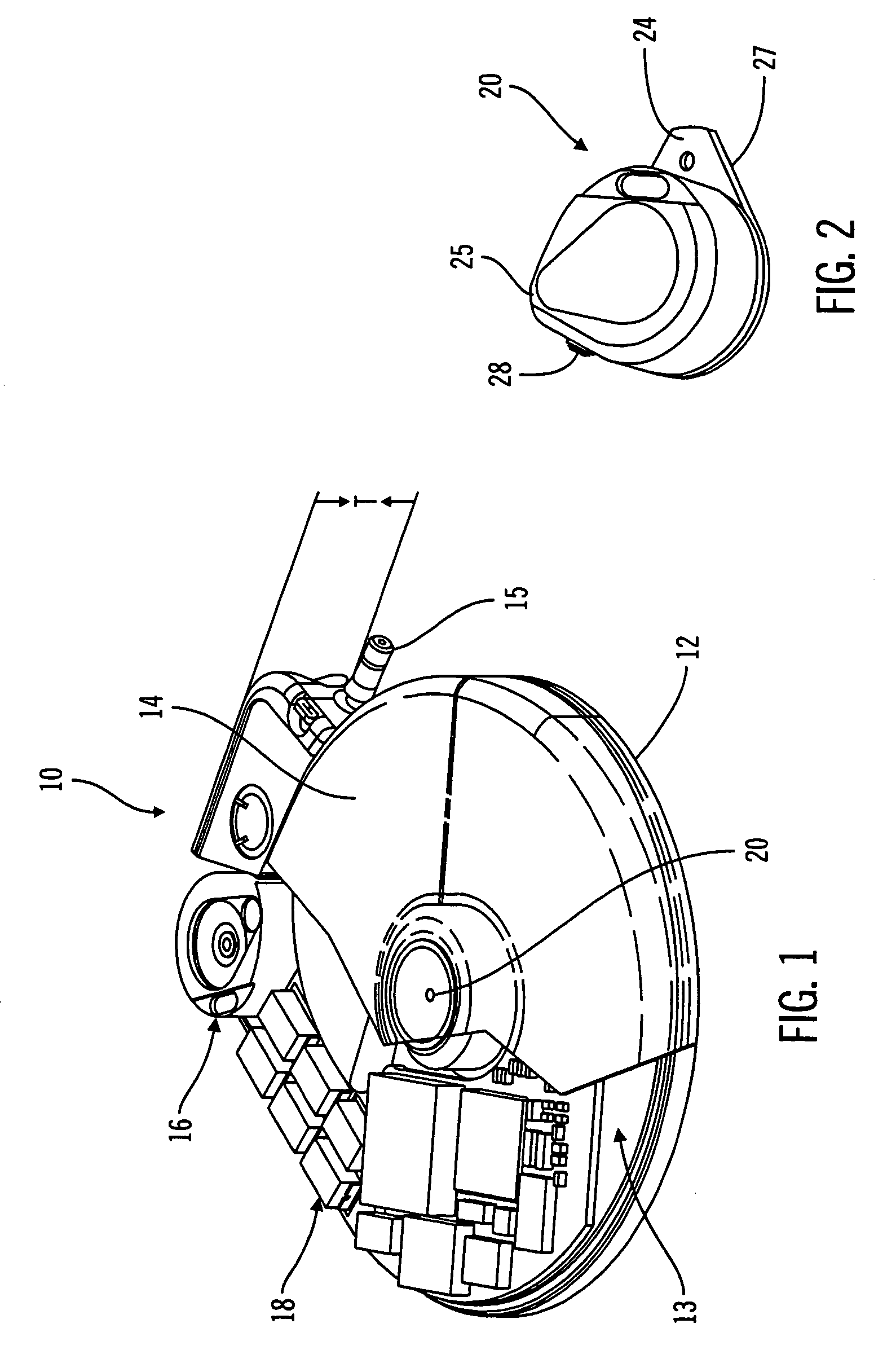
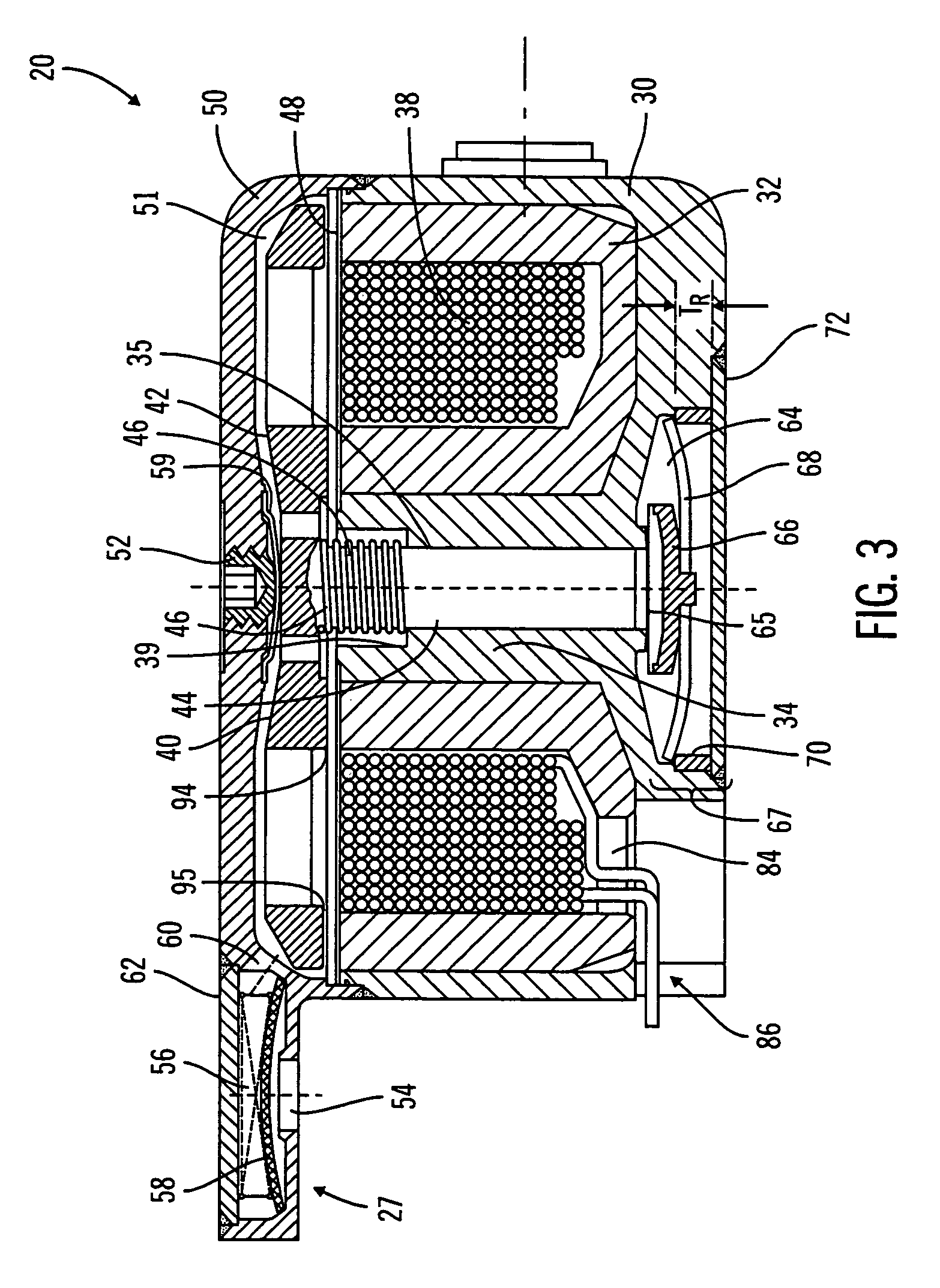
[0046]As discussed above, the present invention relates generally to infusion devices having drive mechanisms and also to drive mechanism configurations for infusion of a medium into a patient or other environment. Preferred embodiments of the invention relate to such devices and drive mechanisms configured for implantation in a patient's body. Configurations described herein allow the drive mechanism and, thus, the infusion device to have a relatively small thickness dimension, for example, to minimize trauma to the implant recipient (referred to herein as the patient). Further preferred embodiments relate to such devices and drive mechanisms ...


PUM


Abstract

A drive mechanism for delivery of infusion medium a coil capable of being electrically activated to provide an electromagnetic field. The coil surrounds a piston channel extending in an axial direction. The piston channel provides a passage for communication of infusion medium to an outlet chamber located at one end of the piston channel. An armature is located adjacent the coil, on one side of the axial channel. The armature is moveable toward a forward position, in response to the electromagnetic field produced by activation of the coil. A piston is located within the piston channel and is moveable axially within the channel to a forward position, in response to movement of the armature to its forward position. The armature and piston are moved toward a retracted position, when the coil is not energized. In the retracted position of the piston, a piston chamber is formed between the piston and a valve member and is filled with infusion medium. As the piston is moved to its forward position, the piston chamber volume is reduced and pressure within the piston chamber increases to a point where the pressure moves the valve member into an open position. When the valve member is in the open position, medium from the piston chamber is discharged into an outlet chamber located on the opposite side of the coil relative to the armature. An outlet is provided in flow communication with the outlet chamber, for discharging infusion medium from the outlet chamber.

Description

CROSS-REFERENCE TO RELATED APPLICATIONS[0001]This application is a divisional of Ser. No. 10 / 033,724, now U.S. Pat. No. 6,770,067 filed Dec. 27, 2001, which is in turn claims the benefit of prior filed U.S. Provisional Application Ser. No. 60 / 317,884, filed Sep. 7, 2001. The entirety of each which are incorporated herein by reference.FIELD OF THE INVENTION[0002]The present invention relates generally to infusion devices, systems and processes and, in particular embodiments to implantable infusion devices, systems and processes employing a drive mechanism configuration which allows the device to have a relatively thin form factor and use power efficiently. Further embodiments of the invention relate to drive mechanisms and processes of making and using such drive mechanisms for infusion devices and systems.RELATED ART[0003]Infusion devices are typically used to deliver an infusion media, such as a medication, to a patient. Implantable infusion devices are designed to be implanted in ...

Claims


Application Information

Patent Timeline
Patent Type & Authority Patents(United States)
IPC IPC(8): A61K9/22A61M1/00A61MA61M5/142A61M5/168A61M37/00
CPCA61M5/14216A61M5/14276A61M2205/8212A61M5/16877
Inventor LORENZEN, ERICGRAY, JOHNBOSLEY, ROBERT
Owner MEDTRONIC MIMIMED INC
Why Eureka
Try Eureka