Method for detecting acoustic emission using a microwave Doppler radar detector

a radar detector and microwave technology, applied in the field of detecting acoustic emission using a microwave doppler radar detector, can solve the problem that the tool wear can be detected during on-line machining operations

Inactive Publication Date: 2008-07-08
SMITH GREGORY C
View PDF3 Cites 23 Cited by
  • Summary
  • Abstract
  • Description
  • Claims
  • Application Information

AI Technical Summary

Benefits of technology

[0071]Therefore, it is a primary object, feature, or advantage of the present invention to improve upon the state of the art.
[0072]It is a further object, feature, or advantage of the present invention to overcome the limitations of current piezoceramic, piezoelectric and laser-interferometry AE sensors.
[0073]Another object, feature, or advantage of the present invention is to provide a method and apparatus for an AE sensor which is economical, yet accurate.
[0074]Yet another object, feature, or advantage of the present invention is to provide an AE sensor appropriate for tool condition monitoring in machining operations as well as other applications.
[0075]These and / or other objects, features, or advantages of the present invention will become apparent from the specification and claims that follow.SUMMARY OF THE INVENTION
[0076]The present invention provides a method of detecting acoustic emissions by detecting acoustic emissions using a microwave Doppler radar detector. The present invention can be used in numerous applications, including detection of tool wear. In such an application, tool wear can be detected during on-line machining operations.

Problems solved by technology

In such an application, tool wear can be detected during on-line machining operations.

Method used


Image

  • Method for detecting acoustic emission using a microwave Doppler radar detector
  • Method for detecting acoustic emission using a microwave Doppler radar detector
  • Method for detecting acoustic emission using a microwave Doppler radar detector

Examples


experiment 1

Results

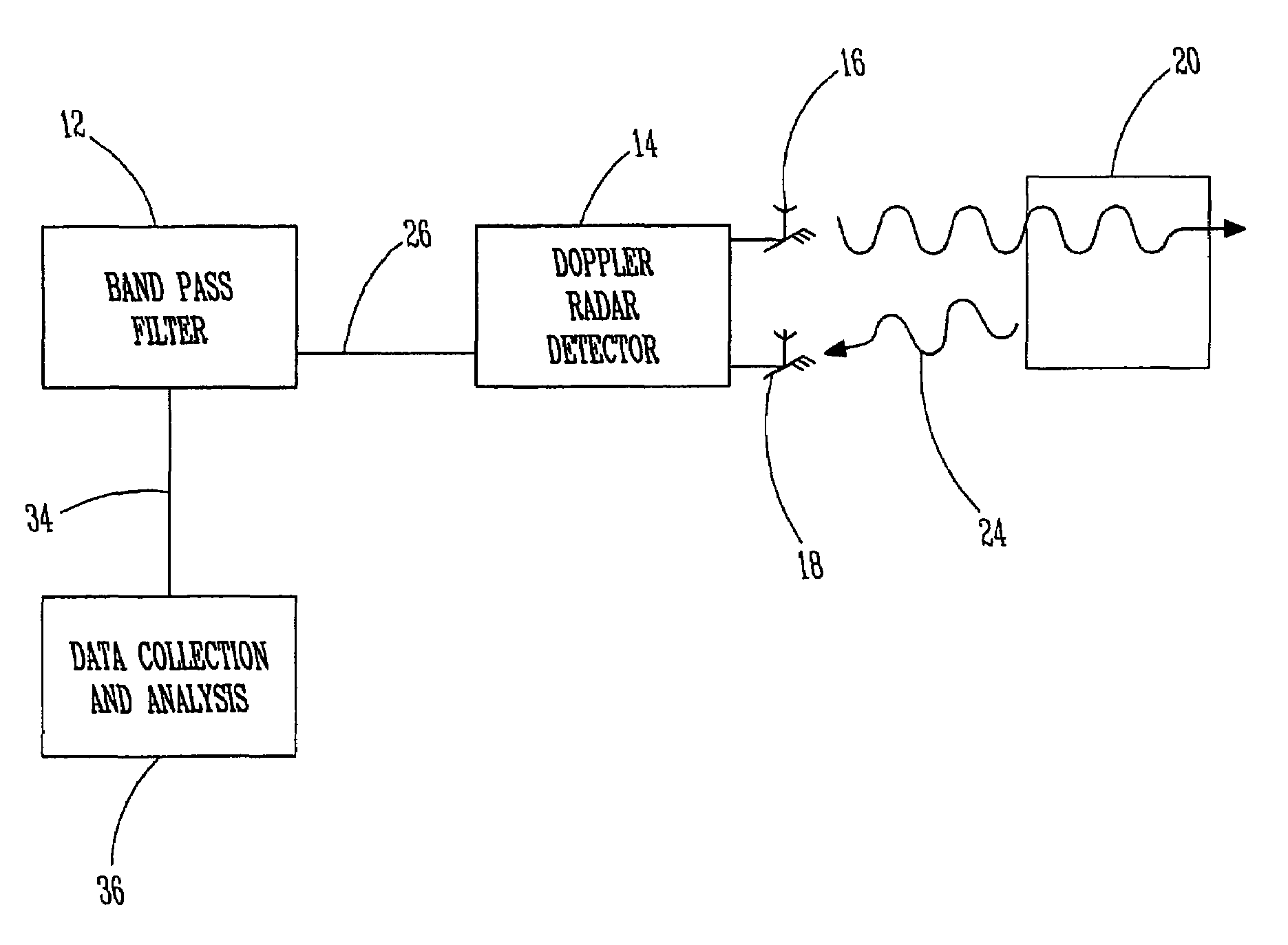
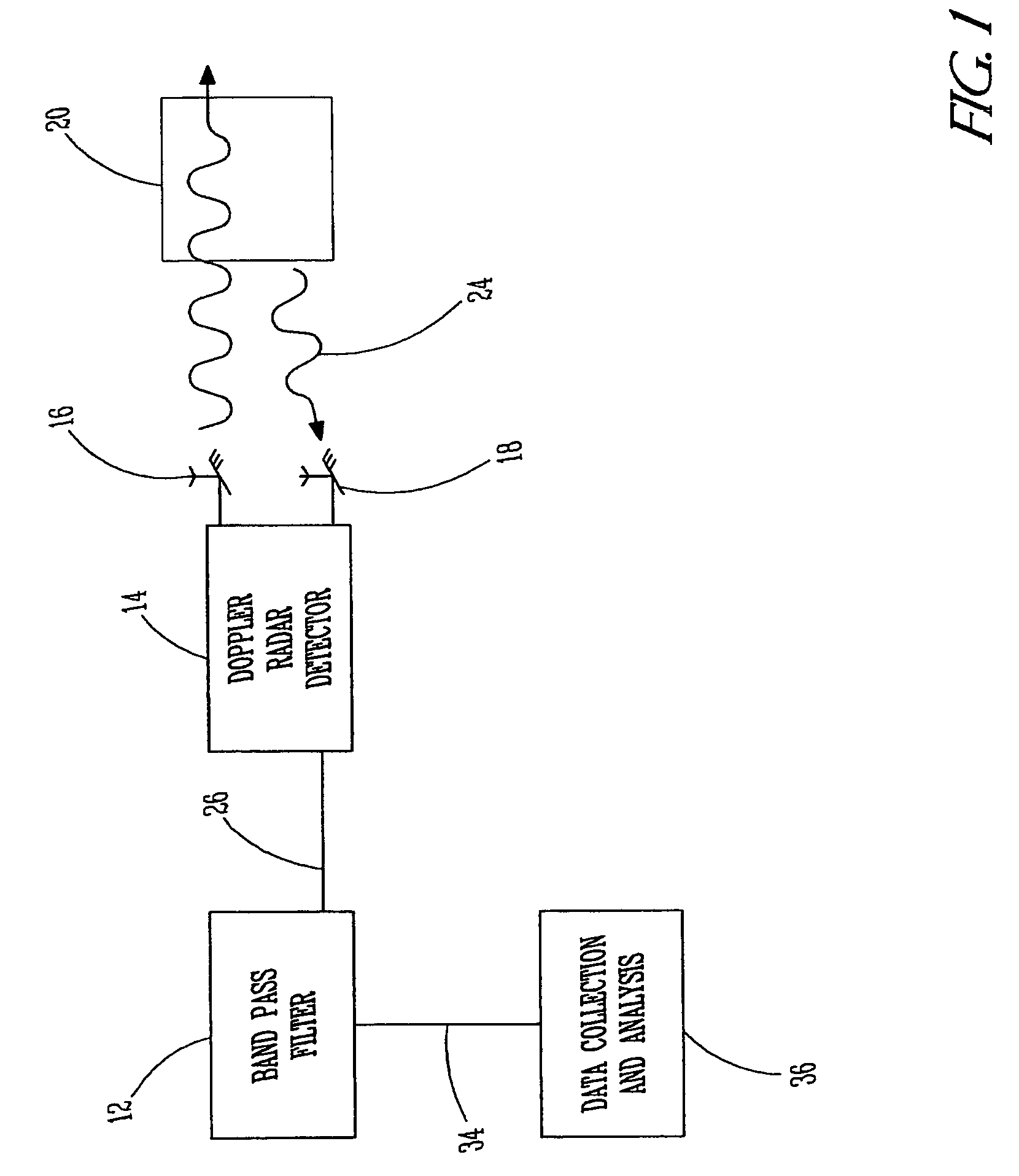
[0113]FIG. 4 shows representative signals generated by the microwave Doppler radar detector 14 and the accelerometer in response to acoustic emission events created by tapping a CNC machine tool insert against a cylindrical aluminum test specimen.

[0114]FIG. 5 shows corresponding power spectra for the signals shown in FIG. 4. The power spectra was computed using MathCAD fft function. While the accelerometer appears to ring at a given frequency, the microwave radar detector 12 and band-pass filter 14 tend to give a more broad-band response, which may more accurately reflect actual characteristics of the AE event.

[0115]As seen in FIG. 4, the Doppler radar detector 14 and band-pass filter 12 detects a secondary AE event, which may be the reflected acoustic wave. If the secondary acoustic emission event is the reflected acoustic wave, then the Doppler radar detector 14 may detect small-scale surface vibrations caused by both the initial tool contact and the reflected acoustic wave...

experiment 2

Results

[0123]FIG. 6 shows representative signals generated by microwave Doppler radar detector 14 and the accelerometer in response to acoustic emission events created by breaking a 0.7 mm mechanical pencil lead on the bottom surface of the test specimen. FIG. 7 shows corresponding power spectra for the signals shown in FIG. 6. Note that, at the given distance of 0.5 feet, output signal level from the microwave Doppler radar detector 14 is roughly ten times that of the accelerometer sensor. As a result, FIGS. 6 and 7 use different scales. These figures show that the two sensors apparently both detect acoustic emission events generated by breaking a 0.7 mm pencil lead on an aluminum test specimen.

[0124]Regression analysis of the data from all fifteen Experiment 2 trials, shown in Table 6, shows evidence of a statistically significant relationship between the natural logarithm of sensor peak-to-peak output voltage and distance between the microwave Doppler radar detector 14 and the te...


PUM

PropertyMeasurementUnit
frequencyaaaaaaaaaa
frequencyaaaaaaaaaa
frequencyaaaaaaaaaa

Abstract

Acoustic emissions are detected by reflecting microwave radar signals off of an object, receiving reflected radar signals, generating an intermediate frequency, and filtering the intermediate frequency to remove low frequency signals associated with object movement and not acoustic emissions. A microwave Doppler radar detector provides the signals, a band-pass filter filters the intermediate frequency signal, and resulting signal is collected and analyzed to establish a relationship between the acoustic emission and the filtered signal. One application described is detecting tool wear using a microwave Doppler-based acoustic emission sensor and predicting tool wear based on the detected acoustic emission.

Description

CROSS-REFERENCE TO RELATED APPLICATIONS[0001]This application is based upon and claims the benefit of priority from Applicant's prior provisional patent application, application U.S. Ser. No. 60 / 564,427, filed Apr. 22, 2004, the entire contents of which are incorporated herein by reference.BACKGROUND OF THE INVENTION[0002]The present invention relates to acoustic emission. More particularly, the present invention relates to detecting acoustic emissions using a microwave Doppler radar detector.1. Acoustic Emission[0003]ASTM E 610-89a (1990) defines acoustic emission (AE) as “the class of phenomena whereby transient elastic waves are generated by the rapid release of energy from a localized source or sources within a material, or the transient elastic waves so generated” (p. 269). Li (2002) states that, “Clearly, an AE is a sound wave or, more properly, a stress wave that travels through a material as the result of some sudden release of strain energy” (p. 157).[0004]Investigators hav...

Claims


Application Information

Patent Timeline
Patent Type & Authority Patents(United States)
IPC IPC(8): G01S13/88G01N29/00B23Q17/09G01S3/80G01S13/524
CPCB23Q17/098G01S13/524G01S13/88
Inventor SMITH, GREGORY C.
Owner SMITH GREGORY C
Why Eureka
Try Eureka