Valve monitoring system and method

a valve monitoring and valve technology, applied in the direction of vibration measurement in solids, instruments, structural/machine measurement, etc., can solve the problems of compressor deterioration, loss of valve performance or complete valve failure, and many monitoring systems available to the compressor industry, while sophisticated, are either costly to install and maintain, and require specialist manpower to collect data, process and analyse, etc., to detect valve anomalies faster, easy to use, and cost-effective

Active Publication Date: 2005-11-24
COMPRESSOR PROD INT
View PDF16 Cites 46 Cited by
  • Summary
  • Abstract
  • Description
  • Claims
  • Application Information

AI Technical Summary

Benefits of technology

[0054] Prior techniques have required more sophisticated analysers to collect data and skilled engineers to analyse it. However, the present invention seeks to provide a more cost effective and simplified process that can detect valve anomalies quicker, more easily and more cheaply.

Problems solved by technology

Because of the mechanical nature of most valves and also due to the harsh environment in which a valve is typically operated, valve components can have limited and unpredictable lifetimes. Furthermore, microscopic faults in valve components that are undetectable at the time of manufacture can grow during use of the component resulting in a loss in valve performance or complete valve failure.
Many monitoring systems available to the compressor industry, while sophisticated, are either costly to install and maintain or require specialist manpower to collect data, process and analyse.
Compressor valves are the most critical parts of a piston compressor and are key to its overall availability, with valve problems reportedly the primary reason for reciprocating compressor shutdowns.
Frequently however, compressor deterioration remains hidden until a costly secondary failure occurs.
The valves may be interconnected in such a way that it is not always possible to identify which valve may have failed or is experiencing problems.
As valves are often mounted in inaccessible or remote areas of a plant, even if a failure is identified, it may take time to locate and change the failed components, possibly resulting in significant losses to the plant.
Typical industrial sites do not employ maintenance engineers full-time, as this can be costly.
The downside of this is that when a compressor failure occurs, an unscheduled shutdown is required until a maintenance engineer resolves the issue.
This can lead to long down-times, as appointments need to be scheduled and parts may need to be ordered, in many cases this disturbs the flow of the production line.
Monitoring is inefficient as it is time and resource-consuming, as well as being prone to human error (it is very possible to mix up valves due to the large number of required measurements).
Collection of data for input into a monitoring system in large sites with many compressors can be very time consuming, and may require multiple operators to cope with the amounts of measurements required.
Indeed, even on sites where there are dedicated maintenance personnel, monitoring is likely to be very low on the list of priorities and in most cases will happen sporadically, possibly once a problem has been identified as opposed to in real time.
Since these shut-downs are generally unscheduled, they end up creating a long period of downtime for the compressor, since a maintenance engineer must be called out to evaluate the situation and repair / replace the damaged parts.

Method used


Image

  • Valve monitoring system and method
  • Valve monitoring system and method
  • Valve monitoring system and method

Examples


Embodiment Construction

[0075] Although many systems and applications are dependent on valves, valves used in engines, compressors and the like are among the most hard worn.

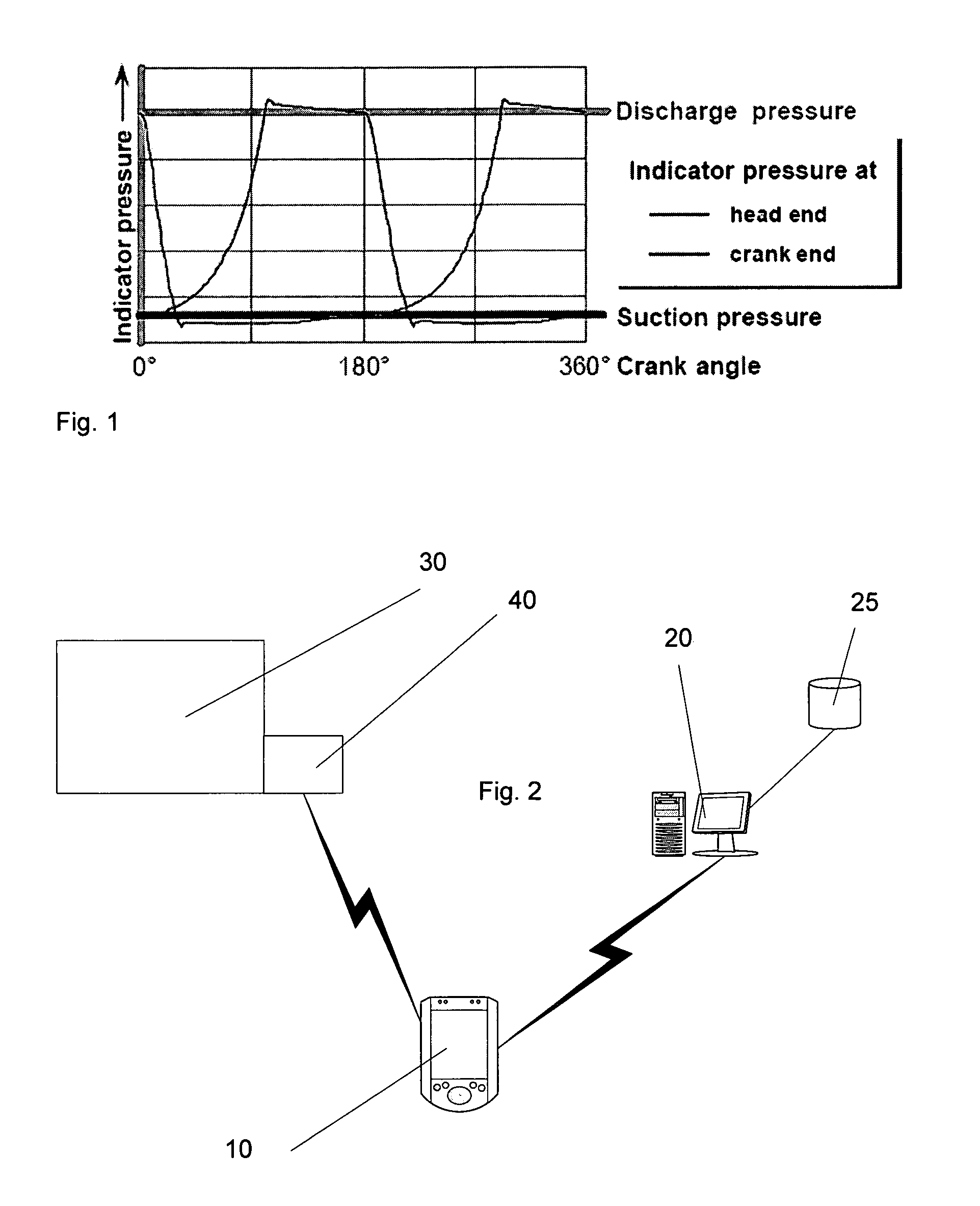
[0076] One type of compressor is known as a reciprocating compressor. A reciprocating compressor has a cylinder shaft that moves in a back and forth motion. These are used in industrial sites, to pump gases or liquids. A compressor has a number of cylinders, each with a number of valves. In the middle, a flywheel, powered by some sort of motor (electric or gas), moves a piston back and forth, repeating its cycle with every rotation. The start of this cycle is known as Top Dead Centre (TDC), occurring at crank angle 0°. At this point, the piston is at the head end of the cylinder.

[0077] As the piston moves towards the crank end, the head-end suction valves open, allowing gas or liquid to flow into the cylinder and the pressure on the crank-end side of the piston forces discharge valves to open, releasing the gas on that side of the pis...


PUM

PropertyMeasurementUnit
crank angleaaaaaaaaaa
frequencyaaaaaaaaaa
areaaaaaaaaaaa

Abstract

A valve monitoring system includes an alert generation system and a memory. The memory encodes baseline acoustic emission data on the valve for a predetermined period of operation. The alert generation system is arranged to receive acoustic emission data for the valve, compare the received acoustic emission data for the valve with the baseline acoustic emission data encoded in the memory and identify valve anomalies in dependence on differences in the received acoustic emission data and the baseline acoustic emission data.

Description

FIELD OF THE INVENTION [0001] The present invention relates to a method and system suitable for monitoring and analysis of valve conditions. BACKGROUND TO THE INVENTION [0002] Valves are used in all manner of machinery to prevent or permit passage of solid, liquid or gaseous matter from one area to another. Because of the mechanical nature of most valves and also due to the harsh environment in which a valve is typically operated, valve components can have limited and unpredictable lifetimes. Furthermore, microscopic faults in valve components that are undetectable at the time of manufacture can grow during use of the component resulting in a loss in valve performance or complete valve failure. [0003] Many monitoring systems available to the compressor industry, while sophisticated, are either costly to install and maintain or require specialist manpower to collect data, process and analyse. [0004] Compressor valves are the most critical parts of a piston compressor and are key to i...

Claims


Application Information

Patent Timeline
Patent Type & Authority Applications(United States)
IPC IPC(8): G01N29/00G01N29/14G01N29/38
CPCG01N29/14G01N2291/2698G01N29/38
Inventor BOKEN, MICHAEL
Owner COMPRESSOR PROD INT
Why Eureka
Try Eureka