

Meniscus head up display combiner
- Summary
- Abstract
- Description
- Claims
- Application Information
AI Technical Summary
Benefits of technology
Problems solved by technology
Method used
Image

Examples
Embodiment Construction
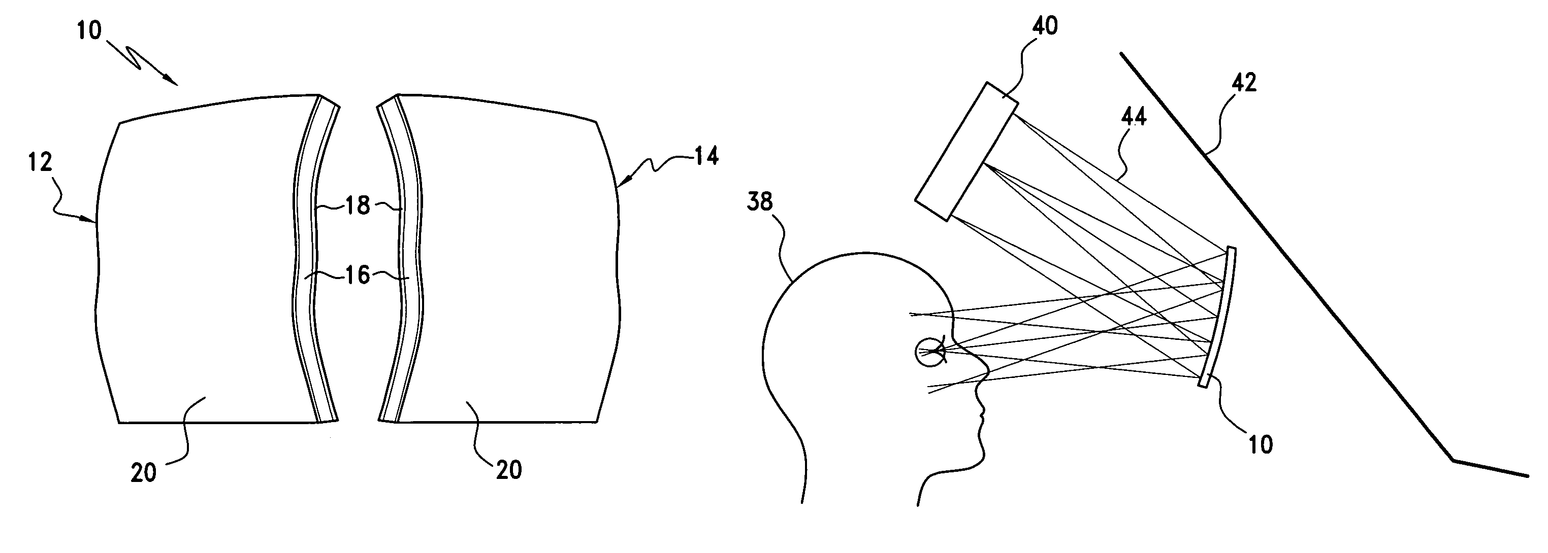
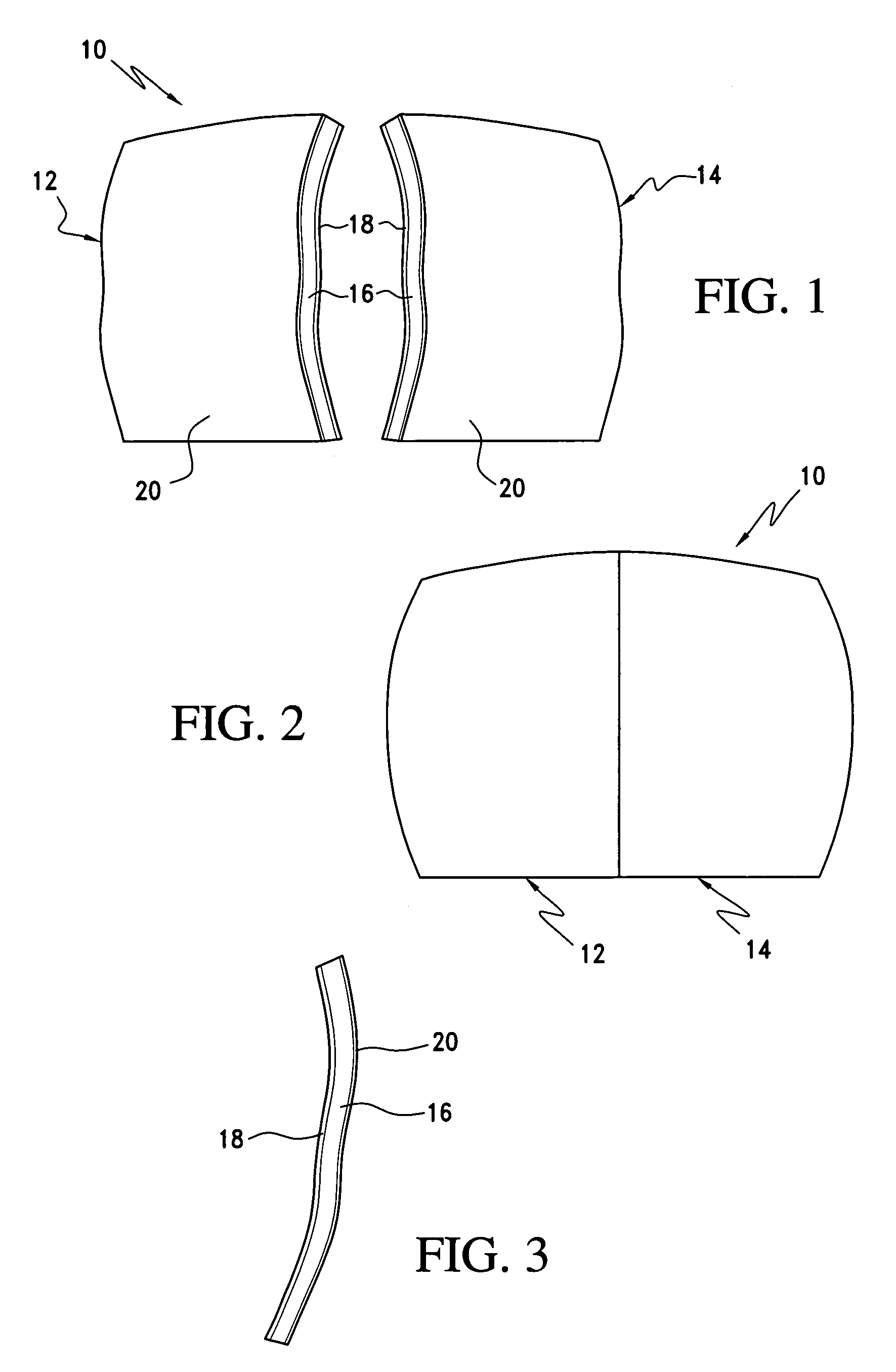
[0027]Referring now to the drawings and the characters of reference marked thereon, FIGS. 1-3 illustrate a first preferred embodiment of the meniscus combiner of the present invention, designated generally as 10. In this embodiment, as shown in FIG. 1, the combiner 10 may be fabricated by using, for example, a pair of lens sections 12, 14. Each lens section 12, 14 includes a meniscus lens 16. A multi-layer dichroic coating 18 is formed on a first surface of each of the meniscus lens sections 12, 14. An anti-reflection coating 20 is formed on a second, opposite surface of the meniscus lens 16. Each lens section 12, 14 is non-symmetric aspheric, i.e. contains non-spherical optical surfaces. Separate sections 12, 14 are bonded with suitable cement and blended together to from a single high performance component, as shown in FIG. 2.
[0028]Utilization of these piecewise aspheric lens sections 12, 14 allows for enhanced freedom in design. The meniscus lens 16 may be formed of a suitable ma...
PUM
 Abstract
Description
Claims
Application Information