X-ray device

a technology of x-ray and x-ray tubes, which is applied in the direction of x-ray equipment, electrical equipment, etc., can solve the problems of storing energy, affecting the operation of the patient, and exposing the patient to unnecessary radiation, and achieves the effect of low power dissipation and loss-fr

Active Publication Date: 2008-07-08
SIEMENS HEALTHCARE GMBH +1
View PDF5 Cites 8 Cited by
  • Summary
  • Abstract
  • Description
  • Claims
  • Application Information

AI Technical Summary

Benefits of technology

[0010]A resonance network is understood as being a network of various electrical components, which is configured such that it comprises at least one resonant transmission frequency. In a resonant transmission frequency, the lowest power dissipation occurs along the transmission line. Thus, for example, in the case of a resonance network configured as a resonant circuit, the capacitive and inductive reactances are theoretically canceled out where there is a resonant transmission frequency, so that a transmission loss only occurs as a result of ohmic resistances. Thus the transmission losses between the inverter and the high voltage generator can be minimized by means of a resonance network.
[0025]The invention offers in particular the advantage of transmission of an AC input voltage of the inverter to a high voltage generator in a manner that is as loss-free as possible. In particular, the X-ray device offers unproblematic spatial separation of the inverter from the high voltage generator. Because of the low power dissipation, the AC input voltage can also be provided in particular using a screened transmission line, which leads directly into the high voltage generator. Advantageously, however, the X-ray device is suitable for a computer tomography scanner in which the high voltage generator and the X-ray source are disposed on a rotating gantry. By using the resonance network, the AC input voltage of the inverter can be supplied to the high voltage generator in a problem-free manner by means of slip rings and in particular without the harmful emission of electric and / or magnetic fields.

Problems solved by technology

In a medical X-ray device in particular, spatial separation of the inverter from the high voltage generator or from the X-ray source is desirable since cumbersome equipment in the vicinity of the X-ray source would restrict the access required when taking an angiogram, for example.
If the high voltage generated by the high voltage generator is supplied to the X-ray source in known proportions over circuits of a corresponding length, this results in high capacitors in the high voltage circuit which cause interference when using pulses, because large amounts of energy are stored.
Disadvantageously, this leads to an exposure of the patient to radiation that is unnecessary because no image is generated.
Furthermore, in the event of collision ionization in an X-ray tube, the stored energy leads to considerable interference with the electronic systems located in the vicinity.
If the high voltage is supplied to the rotating gantry of a computer tomography scanner via slip rings, then the volume of air required for the isolation of the high voltage is very considerable, which involves a considerable disadvantage in terms of costs.
However, this presents the problem already mentioned in the introduction that the further components required to generate the high voltage also have to be mounted on the rotating system, which results in considerable outlay in order to achieve mechanical stability because of the bulk and volumes involved, particular at high rotation speeds.
In such a transmission of the AC input voltage, there disadvantageously occurs a not inconsiderable emission of electric and magnetic fields by the lines from the output of the inverter to the slip ring, which can have a negative influence on the electronic systems in the vicinity.
A further disadvantage in such a transmission is that the power that can be transmitted and the length of the permissible transmission line from the inverter to the high voltage generator are limited by the frequency of the AC input voltage.
This is because, depending on the frequency, voltage drops or transmission losses occur as a result of the inductances and loss resistances present in the lines.

Method used


Image

  • X-ray device
  • X-ray device
  • X-ray device

Examples


Embodiment Construction

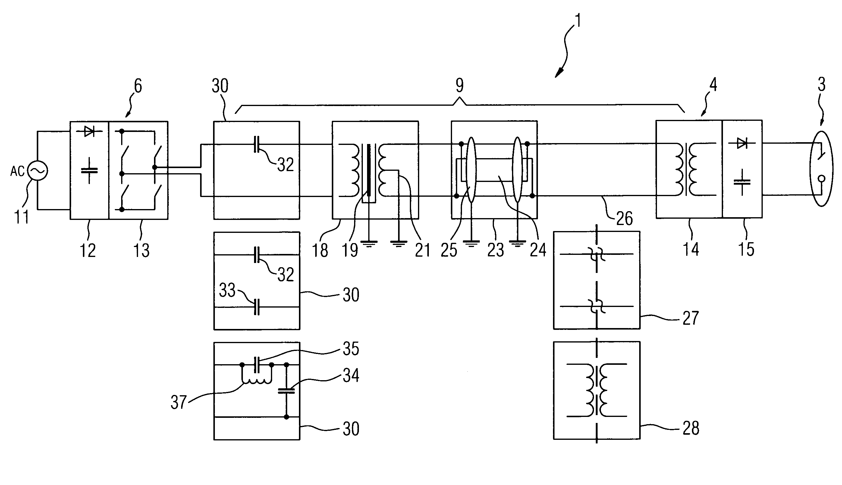
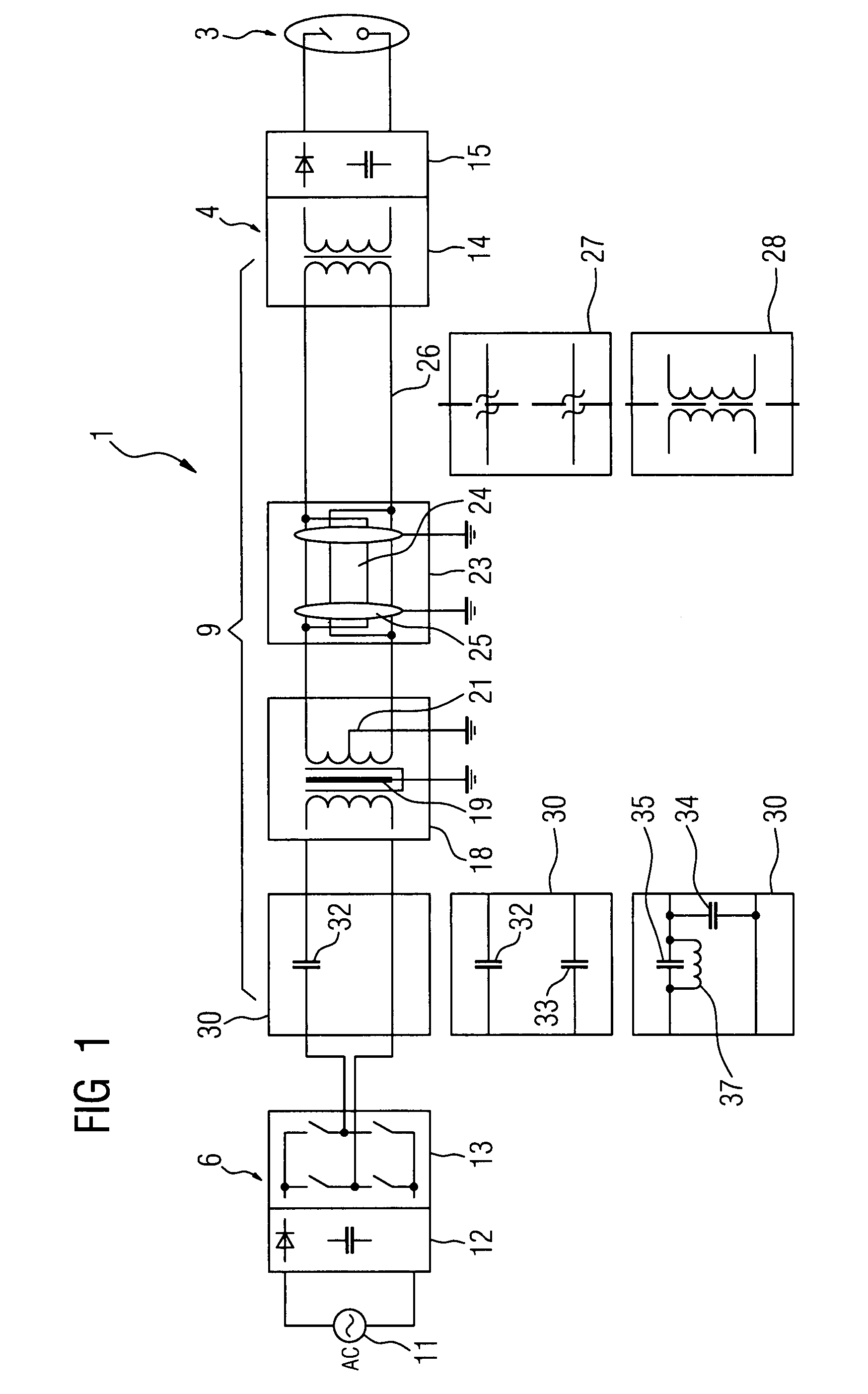
[0029]FIG. 1 shows a diagram of an X-ray device 1, comprising an X-ray source 3, said source being supplied with the required high voltage or energy by a high voltage generator 4. To generate the high voltage, the high voltage generator 4 is connected at the input end to the output of an inverter 6, which generates at the output en d the AC input voltage required by the high voltage generator 4. The inverter 6 is connected to a conventional power supply, shown here by the AC voltage source 11.

[0030]The transmission line between the inverter 6 and the high voltage generator 4 is altogether configured as a resonance network 9, which has a resonant transmission frequency set with maximum output at the operating point of the inverter 6. When an AC input voltage is transmitted at the resonant transmission frequency of the resonance networks 9, there is low power dissipation and low emission of magnetic fields.

[0031]In order to generate the high voltage required by the X-ray source 3, the...


PUM


Abstract

An X-ray device having an X-ray source, a high voltage generator supplying power to the X-ray tube and an inverter to generate, at the output end, an AC input voltage for the high voltage generator is disclosed. Provision is made therein for a resonance network to be formed between the inverter and the high voltage generator. This allows transmission of the AC input voltage with low power dissipation and low radiation levels. It also achieves spatial separation of the inverter from the high voltage generator and the X-ray source.

Description

CROSS REFERENCE TO RELATED APPLICATIONS[0001]The present application claims the benefit of the provisional patent application filed on Mar. 15, 2006, and assigned application No. 60 / 782,720. The present application also claims priority of German application No. 10 2006 011 968.1 filed on Mar. 15, 2006. Both of the applications are incorporated by reference herein in their entirety.FIELD OF THE INVENTION[0002]The invention relates to an X-ray device having an X-ray source, a high voltage generator supplying power to the X-ray tube and an inverter at the output end to generate an AC input voltage for the high voltage generator.BACKGROUND OF THE INVENTION[0003]In such an X-ray device, the inverter usually generates a DC voltage from a network AC voltage in an intermediate circuit, said DC voltage being inverted by means of an inverse rectifier into a higher frequency AC input voltage for the high voltage generator. By means of a transformer and a rectifier, for example, the high voltag...

Claims


Application Information

Patent Timeline
Patent Type & Authority Patents(United States)
IPC IPC(8): H05G1/14H05G1/10H05G1/32
CPCH05G1/10
Inventor BEYERLEIN, WALTER
Owner SIEMENS HEALTHCARE GMBH
Why Eureka
Try Eureka