Communication cable module and transmission loss compensation circuit

a technology of loss compensation circuit and communication cable, which is applied in the direction of transmission, digital transmission, baseband system details, etc., can solve the problems of fluctuation of cross-talk between transmission cables, affecting the transmission speed of the host, and affecting the transmission speed

Inactive Publication Date: 2019-05-21
HITACHI METALS LTD
View PDF17 Cites 1 Cited by
  • Summary
  • Abstract
  • Description
  • Claims
  • Application Information

AI Technical Summary

Benefits of technology

[0003]For example, when an electric transmission cable module (also referred to as a direct attach cable (DAC)) is used for intra-rack or inter-rack communication in a data center, the transmission distance becomes short when the transmission speed increases because the transmission loss in the radio frequency band increases. Accordingly, in recent years, an active copper cable (ACC) module capable of long-distance transmission has been developed and manufactured by mounting a continuous time linear equalizer integrated circuit (CTLE IC) for transmission loss compensation in an electric cable module. The ACC module is desired to be shifted to the idle state when the signal is not input so as to reduce the power consumption and not to output an unnecessary wave that causes a host IC in a device connected thereto to operate erroneously.
[0009]According to the present invention, a communication cable module having a small variation in the output common-mode voltage and the output impedance between the normal operation time and idle time can be provided.

Problems solved by technology

Therefore, when a shift is made to the idle or normal operation according to the method of JP-2009-49672-A, since a large-amplitude common-mode pulse signal exceeding the operating range of the reception host IC is generated and the reception host IC cannot receive data correctly, as a result there is a problem that the communication speed decreases between the hosts.
Further, if the amplitude level is further increased, the reception host IC will be destroyed in the worst case.
In addition, when the shift is made to the idle or the normal operation according to the method of JP-2009-49672-A, the output impedance changes greatly from the differential value 100 ohm to the open end level for example, and thus, in the case of a multi-pair transmission cable module which are formed by bundling a plurality of transmission cables, there is a problem that the cross talk between the transmission cables fluctuates greatly and the communication quality of other lanes deteriorates.

Method used


Image

  • Communication cable module and transmission loss compensation circuit
  • Communication cable module and transmission loss compensation circuit
  • Communication cable module and transmission loss compensation circuit

Examples


first embodiment

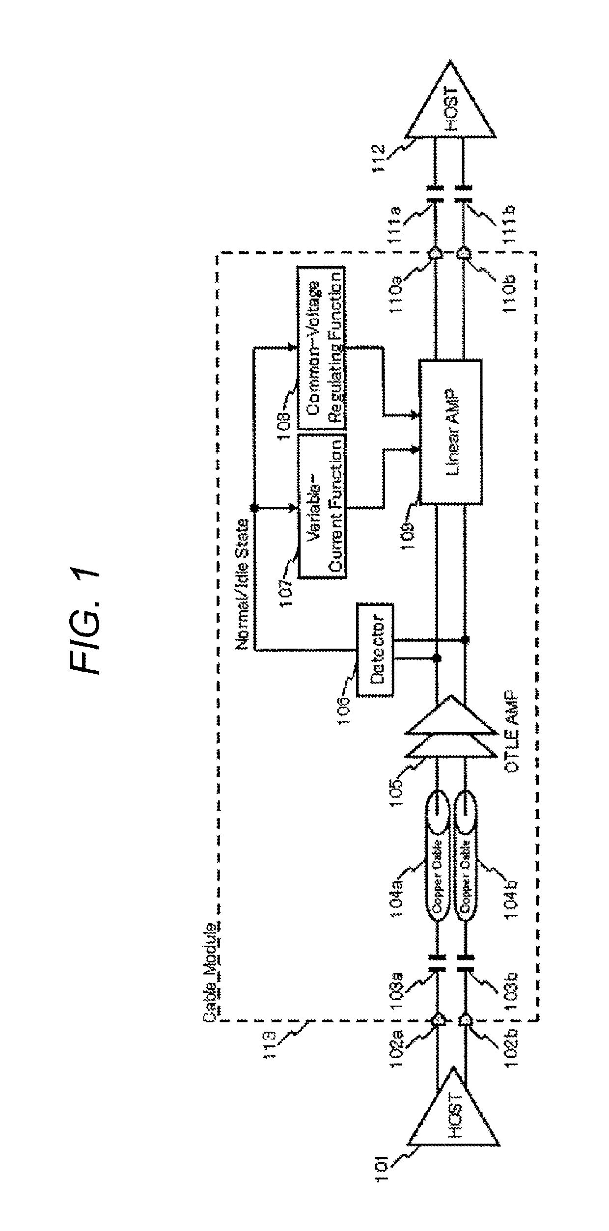
[0019]A first embodiment of the present invention will be described with reference to FIG. 1. A communication cable module 113 shown in FIG. 1 is an ACC and includes input terminals 102a and 102b, AC coupling capacitors 103a and 103b, copper cables 104a and 104b, a CTLE amplifier 105, a detector 106, a variable-current function 107, a common-voltage regulating function 108, a linear amplifier 109, and output terminals 110a and 110b. The communication cable module 113 is inserted between a transmission host IC 101 and AC coupling capacitors 111a and 111b as well as a reception host IC 112, and is used as a communication cable module for mediating communication between the host ICs.

[0020]The differential signal transmitted from the transmission host IC 101 is input into the cable module from the input terminals 102a and 102b, and thereafter, the signal is input into the copper cables 104a and 104b via the AC coupling capacitors 103a and 103b for dividing the operating voltage of the t...

second embodiment

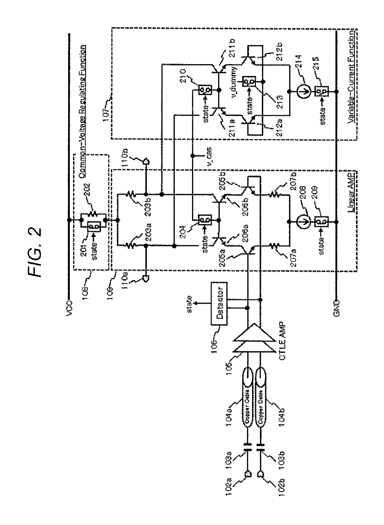
[0031]The second embodiment of the present invention will be described with reference to FIG. 2. The communication cable module shown in FIG. 2 is an ACC, and includes the input terminals 102a and 102b, the AC coupling capacitors 103a and 103b, the copper cables 104a and 104b, the CTLE amplifier 105, the detector 106, the variable-current function 107, the common-voltage regulating function 108, the linear amplifier 109, and the output terminals 110a and 110b.

[0032]The linear amplifier 109 is a general differential cascode amplifier and includes resistors 203a, 203b, 207a and 207b, switches 204 and 209, amplifying transistors 205a and 205b, cascode transistors 206a and 206b, and a current source 208. The output of the CTLE amplifier 105 is input into the bases of the amplifying transistors 205a and 205b. The amplifying transistors 205a and 205b are connected to the resistors 207a and 207b for improving the linearity on the emitter side. The resistors 207a and 207b are connected to ...

third embodiment

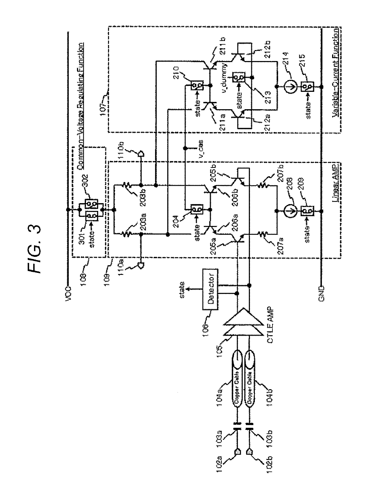
[0045]A third embodiment of the present invention will be described with reference to FIG. 3. The communication cable module shown in FIG. 3 is an ACC and is the same as that of the second embodiment in FIG. 2 except for the configuration of the common-voltage regulating function 108.

[0046]The common-voltage regulating function 108 in the third embodiment is constituted by connecting switches 301 and 302 in parallel. The switch 301 is composed of, for example, a large-size PMOS transistor with a small on-resistance. On the other hand, the switch 302 is composed of a small-size PMOS transistor with a large on-resistance. Hence, if the resistor 202 of the second embodiment is assumed to be the switch 302, the circuits can be regarded as the same circuits. As for the control of each switch, the switches 301, 204, and 209 are turned on and the switches 302, 210, 213, and 215 are turned off at the normal time. The switches 301, 204, and 209 are turned off, and the switches 302, 210, 213,...


PUM


Abstract

There is disclosed a communication cable module including: a conductive cable; a linear amplifier connected to the conductive cable; a detector for detecting presence or absence of an input signal of the conductive cable; a first circuit having a variable-current function; and a second circuit having a common-mode voltage regulating function, wherein when the input signal is not present, the variable-current function of the first circuit reduces an output current of the linear amplifier and the common-mode voltage regulating function of the second circuit regulates an output common-mode voltage of the linear amplifier.

Description

BACKGROUND OF THE INVENTION1. Field of the Invention[0001]The present invention relates to communication cable modules, and particularly relates to a cable module having a small fluctuation in output common-mode voltage and output impedance between operation time and idle time.2. Description of the Related Art[0002]JP-2009-49672-A discloses a technique for reducing a current at the idle time by connecting a switch between a load resistor and a power source (GND) and switching on / off at the operation time and idle time.SUMMARY OF THE INVENTION[0003]For example, when an electric transmission cable module (also referred to as a direct attach cable (DAC)) is used for intra-rack or inter-rack communication in a data center, the transmission distance becomes short when the transmission speed increases because the transmission loss in the radio frequency band increases. Accordingly, in recent years, an active copper cable (ACC) module capable of long-distance transmission has been develope...

Claims


Application Information

Patent Timeline
Patent Type & Authority Patents(United States)
IPC IPC(8): H04L27/04H03F1/00H04L25/02H04L25/03
CPCH04L27/04H03F1/00H04L25/03H04L25/02H03F2200/153H03F1/3211H03F3/45089H03F3/45475H03F3/45484H03F3/45928H03F2200/453H04L25/0272H04L25/0276H04L25/0282
Inventor MAEDA, KOJIFUKASAKU, IZUMIKOKUBO, MASARU
Owner HITACHI METALS LTD
Why Eureka
Try Eureka