Fiber optics fiber inline tap monitoring

a fiber optics and fiber inline tap technology, applied in the field of methods, can solve the problems of high optical loss, large size, high cost, etc., and achieve the effect of improving the efficiency of measuring and collecting tapped light, efficient light guiding, and improving the offset precision of upstream and downstream optical fibers

Inactive Publication Date: 2017-01-03
PHOTONWARES INC
View PDF2 Cites 3 Cited by
  • Summary
  • Abstract
  • Description
  • Claims
  • Application Information

AI Technical Summary

Benefits of technology

[0012]In an aspect of the embodiment, an optical light guide is attached by optical index matching epoxy to the cladding surface of the downstream-side optical fiber and aligned to the splicing offset protruding. The optical light guide is made of optical transparent material with index reflection close or smaller than that of the fiber cladding and has one end polished with an angle to function as a reflector. Index matching epoxy is used to attach and optically couple the light guide/reflector onto the fiber to enable efficient light guiding.
[0013]With mature and improved

Problems solved by technology

But this requires many numbers of mounting steps, resulting in large size, high optical loss, and high cost.
It may also involve breaking the fiber into the air and re-coupling back into the fiber are also high loss and high cost.
Although this design achieves fiber inline tap monitoring, it has major drawbacks of compromising fiber integrity due to micro-bending and no

Method used


Image

  • Fiber optics fiber inline tap monitoring
  • Fiber optics fiber inline tap monitoring
  • Fiber optics fiber inline tap monitoring

Examples


Embodiment Construction

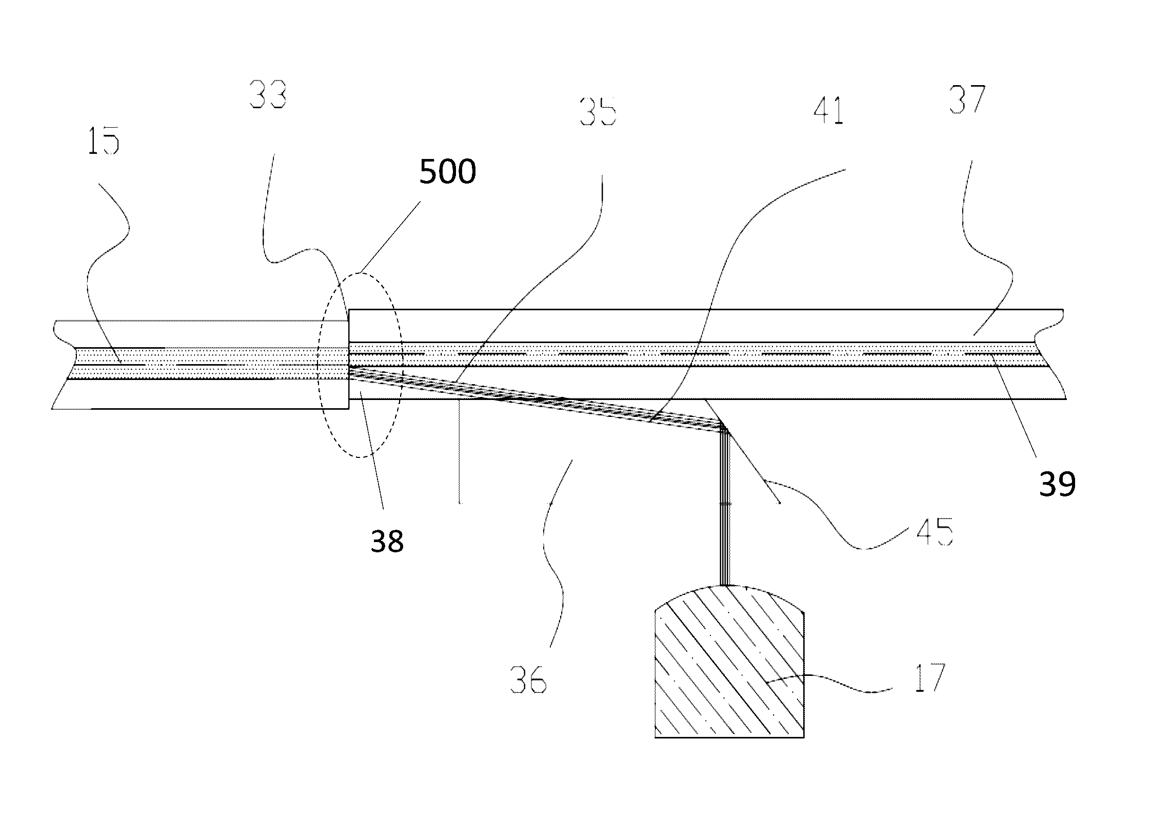
[0028]The numerous innovative teachings of the present application will be described with particular reference to presently preferred embodiments (by way of example, and not of limitation). The present application describes several embodiments, and none of the statements below should be taken as limiting the claims generally. For simplicity and clarity of illustration, the drawing figures illustrate the general manner of construction, and description and details of well-known features and techniques may be omitted to avoid unnecessarily obscuring the invention. Additionally, elements in the drawing figures are not necessarily drawn to scale, some areas or elements may be expanded to help the understanding of embodiments of the invention. For optical fibers, the shadings in the diagram drawings do not necessarily mean to have a higher optical refractive index value, they indicate materials of different optical refractive indexes where optical refractive index value may properly apply...


PUM


Abstract

A method is disclosed to provide improved fiber inline optical power monitoring that eliminates the need for micro-bending the fiber or for fabricating micro-reflector on the fiber. A subset of light is tapped through an offset at a fusion-spliced upstream and downstream optic fiber, and is guided out of the downstream fiber by a light guide to a reflector and photo-sensing measurement. The disclosed inline fiber monitoring is thus cost effective, wavelength independence, reliable, stable, and also causes less light transmission loss.

Description

CROSS-REFERENCE TO RELATED APPLICATIONS[0001]This application claims the priority of the U.S. Provisional Patent Application No. 62 / 268,285, filed on Dec. 16, 2015, the entirety of which is thereby incorporated by reference and for all purposes.BACKGROUND OF THE INVENTION[0002]The present invention relates to a method for coupling optical energy out of an optical fiber, in particular, for fiber optical power monitoring used in mainly in the field of optical communication, optical fiber laser and optical fiber sensors.[0003]Optics fibers have been widely used for increasing telecommunication speed and efficiency, where information is transmitted as light signals through light-transmitting glass or silica fibers. Specially designed optic fibers are also used as fiber optic sensors and fiber optic lasers. They are especially advantageous for long-distance communications, because light propagates through the fiber with little attenuation compared to electrical cables.[0004]Optical perfo...

Claims


Application Information

Patent Timeline
IPC IPC(8): G02B6/42G02B6/255G02B6/28G02B6/35
CPCG02B6/2852G02B6/2835G02B6/4214G02B6/4286G02B6/355G02B6/4201
Inventor ZHAO, JING
Owner PHOTONWARES INC
Why Eureka
Try Eureka