New free electron wire

a free electron wire and wire technology, applied in the field of solid state physics and plasma physics, can solve the problems of loss and reduce the efficiency of electrical appliances, and achieve the effect of excellent commercial future and radical increase of the efficiency of the machin

Active Publication Date: 2013-04-25
FREE ELECTRON ELECTRICALS PTE LTD
View PDF3 Cites 2 Cited by
  • Summary
  • Abstract
  • Description
  • Claims
  • Application Information

AI Technical Summary

Benefits of technology

[0021]Hence this technology will be the backbone of various other technologies already in commercial use. Where ever this technology...

Problems solved by technology

Every material in this world has electrical resistance which is responsible for huge loss of energy...

Method used


Image

  • New free electron wire
  • New free electron wire
  • New free electron wire

Examples


Embodiment Construction

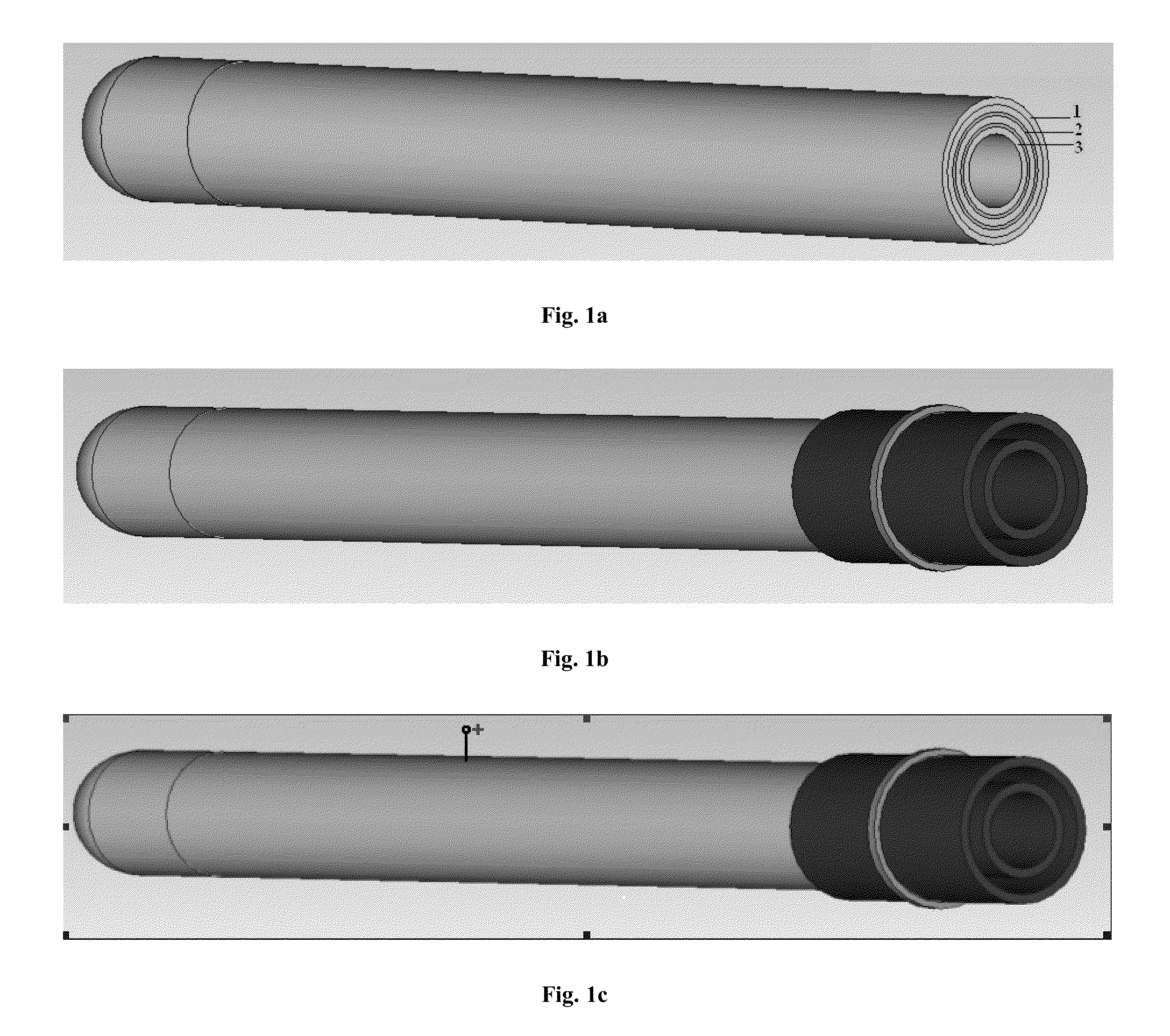
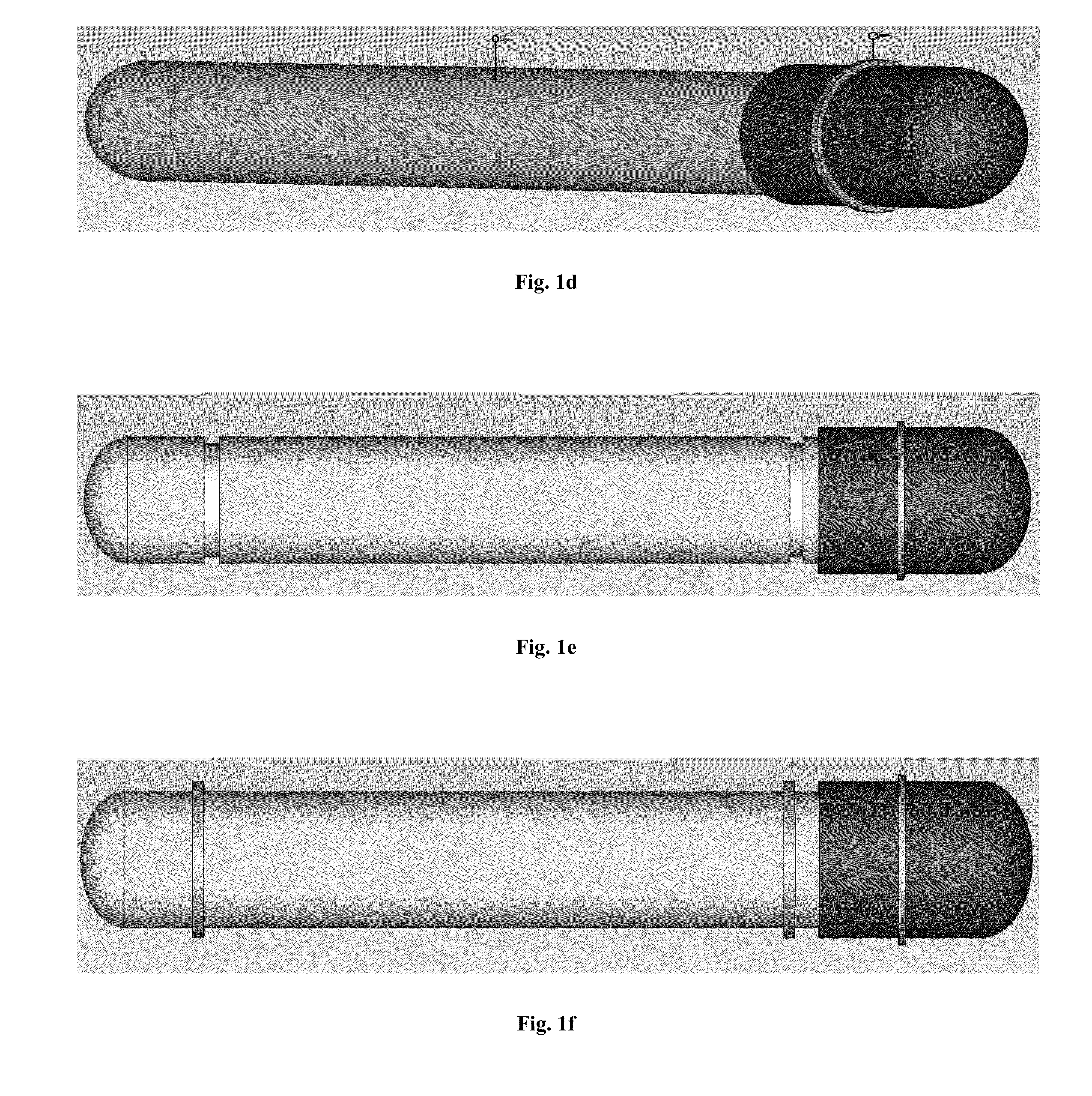
[0034]For our own convenience and to conduct a sample test with ease let us take a vacuum tube of cylindrical shape of length 1 meter or 1000 mm, and 2 cm or 20 mm in diameter and made up of alternate layers of Teflon and Silicon Oxynitride. We will proceed with our calculation on this and we will see that our calculation will be proved to be effective in this lm long with 2 cm diameter tube. Hence if we proceed by increasing the length and put the increased length values in the mathematical equations, we will see that it still works. Hence it will work even if the tube is 100 s of kilometres long for real transmission lines.

[0035]Also there are two identical copper coils on both ends of the proposed wire to deliver electrical energy in the form of an Alternating Current (A.C) and to recollect that electricity for commercial use or to test the efficiency of the wire after the AC gets transported to the other end of the wire.[0036]In this sample calculation we will taste the wire wit...


PUM


Abstract

This invention relates to New Free Electrons Wire (4a, b), which will enable the use of electrical energy and also energy in various other forms in a loss free way at room temperature. Free Electrons confined in vacuum (4a1) at the order of 10−4 torr or more, at the core of the wire, can move a distance as long as about, to a few kilometers without any collision. The vacuum is maintained in a tube made up of alternate layers of Teflon (4a2) and Silicon Oxynitride (4a3) The columbic repulsion between these free electrons (4b1, 4b2, 4b3 . . . ) will actually conduct energy without any loss. The free electrons trapped in vacuum tube (4a), should be at a particular density of around 2.02×10⁸ electrons in the area covered by the input device (4b4) or output device (4b5) and also all along the Free Electron Wire. The input device (4b4) is to deliver energy to the free electrons (4b1, 4b2, 4b3 . . . ) of the New Free Electrons Wire (4a, b), for loss free transportation and various other uses of energy. The output device (4b5) on the other end or anywhere on the wire, is to recollect the energy from the free electron wire, for different uses. The density of the electrons, inside the vacuum tube (4a) can be varied by changing the potential at the metal encapsulation of the wire and hence the covered are of the Input device (4b4) and the output device (4b5) over the free electron wire (4a, b) should also be changed. The covered are of the Input device (4b4) and the output device (4b5) over the free electron wire (4a, b) bears a definite ratio with the free electrons (4b1, 4b2, 4b3 . . . ) of the wire. Finally there will be a metal encapsulation(s) (4a4) over the wire to keep the electromagnetic field remain confined within the free electron wire (4a, b) to make it harmless in all respect to the health of living creatures, who may come in close contact with the wire. Apart from energy transportation the free electron (4a, b) wire is also capable of generating very high electromagnetic field generated by these free electrons (4b1, 4b2, 4b3 . . . ), simply by removing the metal encapsulation(s) (4a4), which can be used for various other electrical and non-electrical purposes. The materials and techniques adopted to create this New Free Electron Wire (4a, b) will enable it to get produced commercially at the cost of general copper wires.

Description

CROSS REFERENCE TO RELATED APPLICATIONS Prior Arts[0001]Free Electron laser (FEL): Unlike FEL this invention uses free electrons as energy carriers or uses the fundamental properties of free electrons to transported and use of energy in a loss free way. It has nothing to do with the radiation or dissipation of any kind of energy apart from using the varying electromagnetic flux generated by the free electrons of the wire in acceleration and to recollect energy from the wire; whereas FEL deals with the optical energy radiated by the accelerated free electrons only and this invention doesn't deal with the optical energy generated by the accelerated free electrons in any way. Also the invention of “New Free Electron Wire” uses confined electrons and not dynamic electrons like FEL. Hence there is a huge fundamental difference between the two.[0002]Klystron: This invention relates to a vacuum tube containing an electron gun, aresonator that changes the velocity of the electron beam in ac...

Claims


Application Information

Patent Timeline
IPC IPC(8): H05K5/06H01R13/02H01B13/00
CPCH01B13/00H01L39/005H05K5/06H01R13/02H10N60/99H01B12/00H01J21/00H10N60/00H10N60/80
Inventor HALDAR, SABYASACHI
Owner FREE ELECTRON ELECTRICALS PTE LTD
Why Eureka
Try Eureka