Method for machining slide core hole and measurement/correction system for use in machining of slide core hole

Active Publication Date: 2008-08-21
TOSHIBA MASCH CO LTD
View PDF5 Cites 21 Cited by
  • Summary
  • Abstract
  • Description
  • Claims
  • Application Information

AI Technical Summary

Benefits of technology

[0014]According to the present invention, machining of a slide core hole in a mold, which has conventionally been carried out in a labor-intensive manner by a skilled worker, can be carried out efficiently by utilizing the high-speed cutting performance of a five-axis machine tool and, in addition, all the machining steps can be carried out by NC machining. This can eliminate, for example, adjustment o

Problems solved by technology

While a significant improvement in high-speed, high-precision machining has been achieved as described above, old-fashioned machining operations are still practiced, and the imbalance is becoming a problem.
This often causes a phase misalignment between the core pocket and the rod hole, resulting in poor fitting of an insert into the core pocket.
While a core pocket a

Method used


Image

  • Method for machining slide core hole and measurement/correction system for use in machining of slide core hole
  • Method for machining slide core hole and measurement/correction system for use in machining of slide core hole
  • Method for machining slide core hole and measurement/correction system for use in machining of slide core hole

Examples


Embodiment Construction

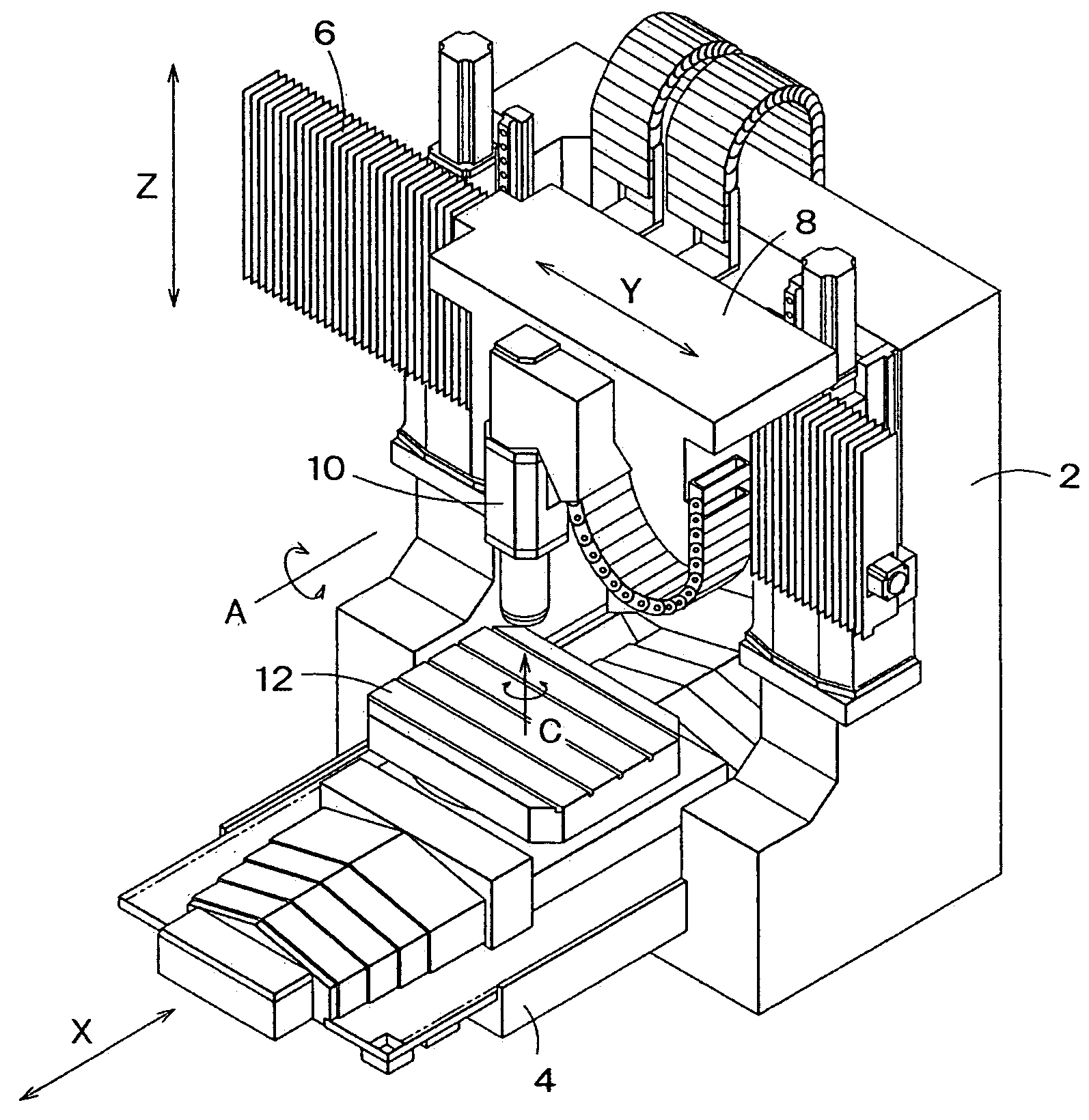
[0026]A method for machining a slide core hole and a measurement / correction system for use in carrying out the machining of the slide core hole, according to the present invention, will now be described with reference to the drawings. FIG. 1 shows a bridge-type machine tool, an exemplary five-axis machine tool for use in machining of a slide core hole according to the present invention.

In FIG. 1, reference numeral 2 denotes a pair of columns and reference numeral 4 denotes a bed. A cross rail 6, bridging the columns 2 and extending horizontally, is mounted to the columns 2. The cross rail 6 is designed to be vertically movable. A saddle 8 is horizontally movably mounted to the cross rail 6. A spindle head 10 is pivotably mounted on the saddle 8 and is driven by a swivel pivot mechanism supported by a pivot rolling guide.

[0027]A table 12 is provided on the bed 4. The table 12 is a rotary table capable of 360-degree successive rotation, and is capable of turning a workpiece on the tab...


PUM

PropertyMeasurementUnit
Angleaaaaaaaaaa

Abstract

There are provided a method for machining a slide core hole and a measurement/correction system for use in machining of a slide core hole, which enable efficient machining of a slide core hole while utilizing the high-speed cutting performance of a five-axis machine tool. The method for machining an inclined slide core hole, comprised of a core pocket and a rod hole, in a mold as a workpiece by means of a five-axis machine tool having, in addition to X-axis, Y-axis and Z-axis, an A-axis for pivoting of a spindle head and a C-axis for rotation of a table, includes the steps of: pivoting the spindle head to meet the inclination angle of the slide core hole to be machined in the mold, and fixing the A-axis angle; spot-facing a shallow flat-bottomed spot-faced hole in the surface of the mold by using an end mill as a tool; drilling a guide hole in the bottom surface of the spot-faced hole by using a drill or a reamer as a tool; drilling said rod hole by using a gun drill as a tool with the guide hole as a guide for the gun drill; carrying out, as pre-machining before machining of said core pocket, shaping machining to form an intermediate pocket hole while expanding the spot-faced hole by using an end mill as a tool; correcting a reference point for use as a reference in machining of the core pocket based on measurement of the shape of the intermediate pocket; and executing a corrected machining program with the corrected reference point to carry out precision shaping machining of the core pocket while expanding the intermediate pocket by using an end mill as a tool.

Description

BACKGROUND OF THE INVENTION[0001]1. Field of the Invention[0002]The present invention relates to a method for machining a slide core hole and a measurement / correction system for use in machining of a slide core hole, and more particularly to a technique for machining with a five-axis machine tool an inclined slide core hole for an extrusion pin in a mold for use in molding of a large-sized resin product, such as an instrumental panel or a bumper of an automobile.[0003]2. Background Art[0004]A bridge-type machine tool is conventionally known as a typical five-axis machine tool. A bridge-type machine tool includes a spindle head provided on a cross rail and has, in addition to X-axis, Y-axis and Z-axis, an A-axis for pivoting of the spindle head and a C-axis for indexing of a table. An example of such a bridge-type machine tool is disclosed in Japanese Patent Laid-Open Publication No. 2004-34168. Five-axis machine tools, including the bridge-type machine tool, have been advantageously...

Claims


Application Information

Patent Timeline
IPC IPC(8): B23B35/00
CPCG05B19/402G05B2219/36201Y10T408/03G05B2219/49113G05B2219/45204B23Q15/22B23Q17/2233
Inventor KATOH, KOUICHIITOH, TAKAMASAFUJITA, TSUYOSHIUSUI, MASARU
Owner TOSHIBA MASCH CO LTD
Why Eureka
Try Eureka