Sintered ring magnet and method of manufacturing the same

a technology of sintered rings and rings, which is applied in the field of radially oriented sintered rings, can solve the problems of deterioration of a magnetic alignment property, reduction of the alignment coefficient of magnetic powder, and inability to achieve a high magnetic property

Inactive Publication Date: 2006-03-09
MITSUBISHI ELECTRIC CORP
View PDF3 Cites 21 Cited by
  • Summary
  • Abstract
  • Description
  • Claims
  • Application Information

AI Technical Summary

Benefits of technology

[0018] These and other objects, features and advantages of the invention will become more apparent upon reading the following detailed description along with the accompanying drawings.

Problems solved by technology

A problem encountered when pressing magnetic powder in a magnetic field for producing an axially elongate ring magnet is that a sufficient field strength of alignment field is not obtained, resulting in a reduction in alignment coefficient of the magnetic powder and an inability to achieve a high magnetic property.
It is commonly known that a problem occurs due to deterioration of a property of magnetic alignment when pressing a ring magnet in a magnetic field if the ring magnet has an axial length larger than a value of H given by equation (2) above.
A chronic problem encountered in the manufacture of a sintered ring magnet is that the powder compact does not shrink uniformly but becomes deformed as a result of shrinkage during sintering operation.
Since a ring magnet is produced by making multiple layers of powder compacts by carrying out these sequential steps, the method of Japanese Patent Application Publication No. 1990-281721 leads to low manufacturing productivity.
Also, since all these steps are performed in the pressing machine, there exist various limitations in operation in the individual steps.
Furthermore, the powder compacts in lower layers are pressurized more times than those in upper layers, magnetic alignment is disturbed in the lower-layer powder compacts, inevitably causing deterioration of magnetic properties.
Moreover, this ring magnet manufacturing method is associated with a problem that the magnetic properties deteriorate at each boundary region between the adjacent powder compacts due to the influence of the powder compact in a lower layer.
The aforementioned method of Japanese Patent Application Publication No. 2001-335808 has a problem that the compact restraining jig is a consumable and it is necessary to set the compact restraining jig with a central axis thereof precisely aligned with a central axis of the ring-shaped powder compact, resulting in low manufacturing productivity.

Method used


Image

  • Sintered ring magnet and method of manufacturing the same
  • Sintered ring magnet and method of manufacturing the same
  • Sintered ring magnet and method of manufacturing the same

Examples


first embodiment

(1) Structure of the Sintered Ring Magnet of the First Embodiment

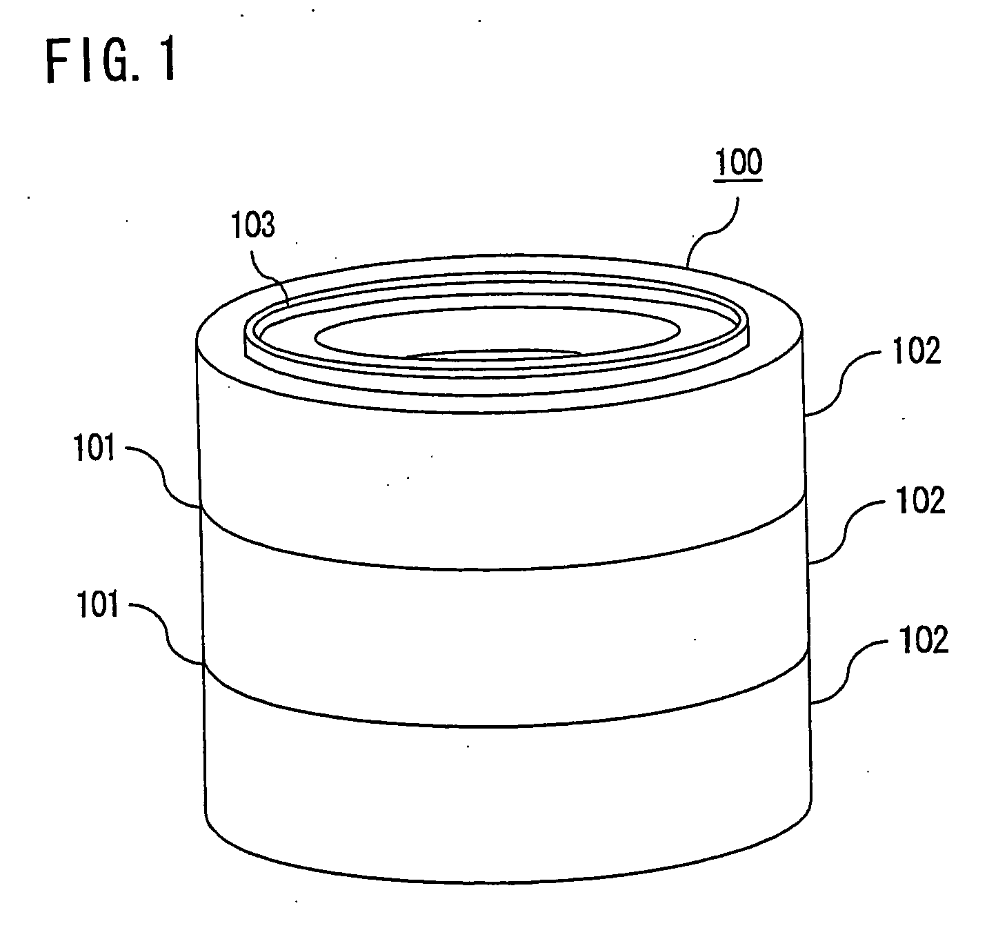
[0045] First, the structure of a sintered ring magnet 100 according to a first embodiment of the invention is described with reference to FIG. 1 which is a perspective view of the sintered ring magnet 100.

[0046] Referring to FIG. 1, the sintered ring magnet 100 of the embodiment is a ring magnet produced by stacking a plurality of ring-shaped powder compacts 102 in layers (three layers in the illustrated example) in an axial direction and joining the ring-shaped powder compacts 102 by sintering the stacked ring-shaped powder compacts 102. The individual ring-shaped powder compacts 102 are joined at boundaries 101 as a result of sintering operation, together forming a single structure. As depicted in FIG. 1, there is formed a ring-shaped protruding part 103 on an upper end surface of the ring-shaped powder compact 102 in an uppermost layer of the sintered ring magnet 100 in this embodiment. Although not illustrated, ...

second embodiment

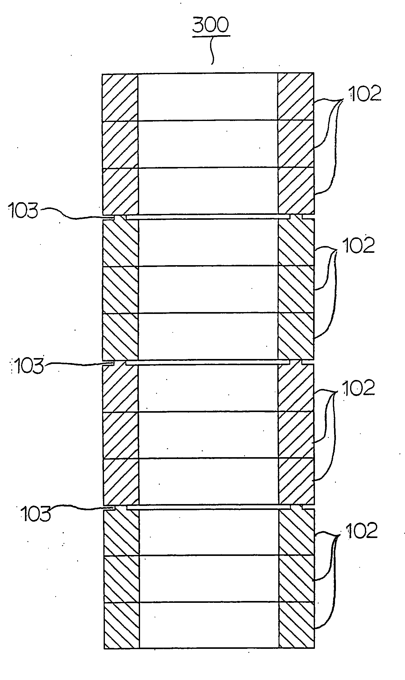
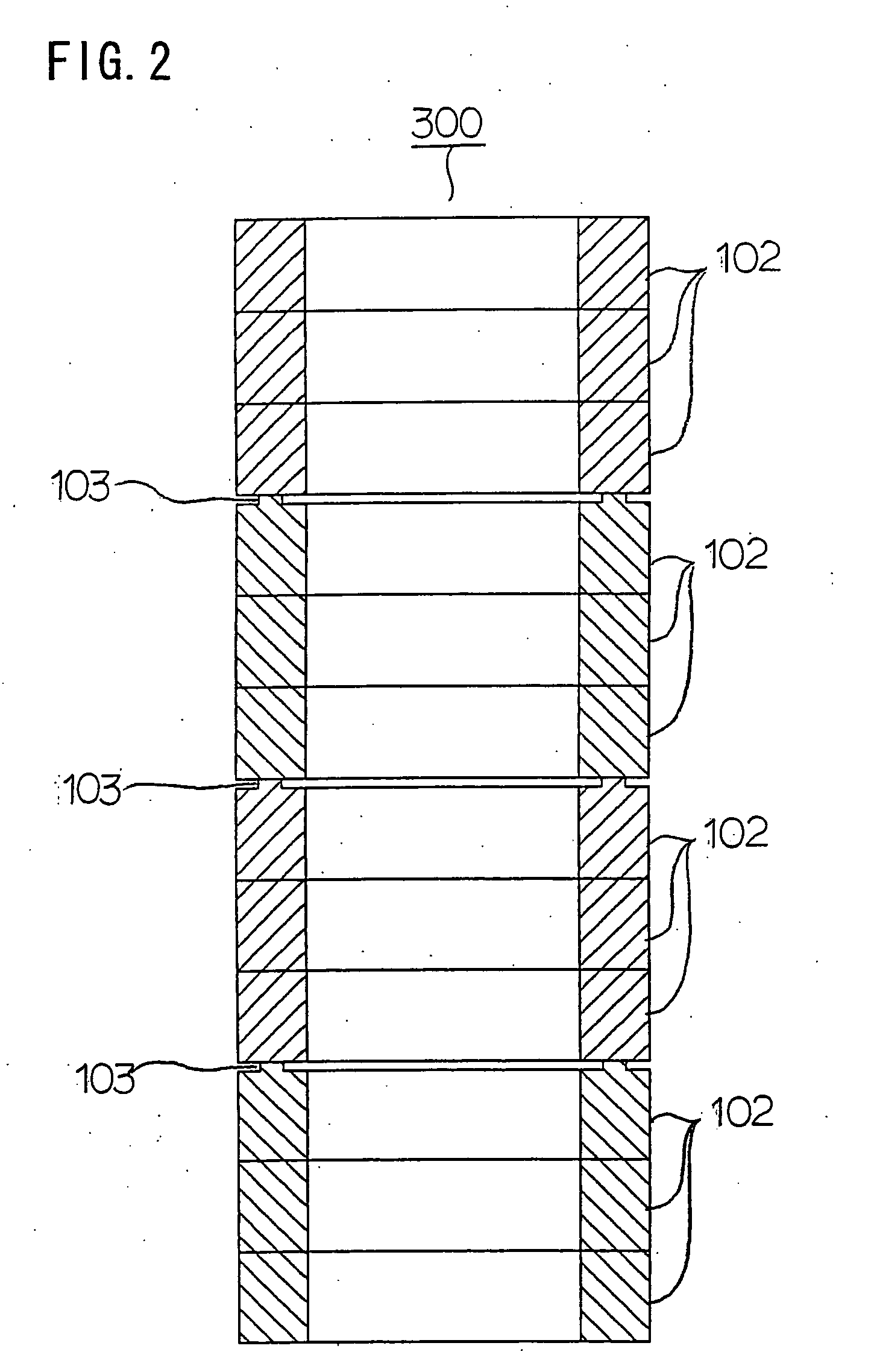
[0100]FIG. 22 is a cross-sectional view of a sintered ring-shaped powder compact rod 301 obtained by a method of manufacturing sintered ring magnets according to a second embodiment of the invention. FIG. 23 is a cross-sectional view of the sintered ring magnets obtained by dividing the sintered ring-shaped powder compact rod of FIG. 22. Specifically, a curved inner surface and a curved outer surface of the sintered ring-shaped powder compact rod 301 formed by sintering a plurality of ring-shaped powder compacts 102, 102B are finished by machining, and the sintered ring-shaped powder compact rod 301 is subjected to an anticorrosion surface treatment. Then, a mechanical bending stress is applied to boundary regions of the sintered ring-shaped powder compact rod 301 and, as a result, the sintered ring-shaped powder compact rod 301 breaks at the boundary regions where ring-shaped protruding parts 103 are formed and the sintered ring magnets of the second embodiment are obtained as show...

third embodiment

[0103]FIG. 24 is a cross-sectional view of a sintered ring-shaped powder compact rod 302 obtained by a method of manufacturing sintered ring magnets according to a third embodiment of the invention. Referring to FIG. 24, alumina powder 104 having an average particle size between 1 micrometer and 100 micrometers is dusted to a thickness between 1 micrometer and 100 micrometers in specific boundary regions of ring-shaped powder compacts 102 which are stacked one on top of another for forming the sintered ring-shaped powder compact rod 302. The alumina powder 104 is dusted in half or less of the area of each boundary region.

[0104] The ring-shaped powder compacts 102 used for producing the sintered ring-shaped powder compact rod 302 of the third embodiment are made by substantially the same manufacturing method as explained earlier with reference to the first embodiment. For example, to produce the sintered ring-shaped powder compact rod 302 of FIG. 24, three ring-shaped powder compact...


PUM

PropertyMeasurementUnit
thicknessaaaaaaaaaa
thicknessaaaaaaaaaa
particle sizeaaaaaaaaaa

Abstract

A ring magnet manufacturing method includes the steps of stacking a plurality of radially oriented ring-shaped powder compacts (102) in an axial direction thereof to produce a ring-shaped powder compact rod, sintering the ring-shaped powder compact rod to produce a sintered ring-shaped powder compact rod (300) in which the ring-shaped powder compacts (102) are joined together, and dividing the sintered ring-shaped powder compact rod (300). In this ring magnet manufacturing method, protruding parts (103) are formed on upper end surfaces of the ring-shaped powder compacts (102) which will be located in uppermost layers of individual sintered ring magnets (100), for example, such that the ring-shaped powder compacts (102) are joined with a reduced joint strength at specific boundary regions of the sintered ring-shaped powder compact rod (300) where the protruding parts (103) are located than at the other boundary regions. The sintered ring magnets (100) are obtained by dividing the sintered ring-shaped powder compact rod (300) at the specific boundary regions having the reduced joint strength.

Description

BACKGROUND OF THE INVENTION [0001] 1. Field of the Invention [0002] The present invention relates to a radially oriented sintered ring magnet used in compact motors, for instance, and a method of manufacturing the radially oriented sintered ring magnet. [0003] 2. Description of the Background Art [0004] A radially oriented anisotropic ring magnet is often used in permanent magnet motors. It is common practice to use an axially elongate ring magnet when manufacturing a compact high-power motor having a small inertia. [0005] A problem encountered when pressing magnetic powder in a magnetic field for producing an axially elongate ring magnet is that a sufficient field strength of alignment field is not obtained, resulting in a reduction in alignment coefficient of the magnetic powder and an inability to achieve a high magnetic property. [0006] When a ring magnet is radially oriented magnetically, a magnetic flux passing through a core of a metal die unit for pressing magnetic powder in...

Claims


Application Information

Patent Timeline
Patent Type & Authority Applications(United States)
IPC IPC(8): B22F7/02B22F3/00B22F3/24B22F5/00B22F7/06H01F1/08H01F7/02H01F41/02H02K15/03
CPCB22F5/003B22F2998/00H01F1/086H01F41/0266H01F41/028B22F5/106
Inventor UGAI, YOSHIKAZUIWAMI, TAIZONAKAHARA, YUJIYAMASHIRO, SATOSHI
Owner MITSUBISHI ELECTRIC CORP
Why Eureka
Try Eureka