This helps you quickly interpret patents by identifying the three key elements:
Problems solved by technology
Method used
Benefits of technology
Benefits of technology
[0010]A principal object of the present invention is to provide a manufacturing method capable of obtaining a liquid ejection head in which flow passages and ejection outlets are formed with good shape accuracy.
[0018]According to the present invention, it is possible to provide a liquid ejection head in which the flow passages and the ejection outlets have been formed with good shape accuracy, with high reproducibility.
Problems solved by technology
However, in this case, waviness by the influence of a stepped portion between the flow passage pattern and the substrate can occur, so that a thickness after the application is not uniform to result in a non-uniform height of an ink ejection outlet forming portion.
As a result, a distance from a heat generating resistor for ink ejection to the ink ejection outlet (═OH distance) is non-uniform in some cases.
Further, it is also assumed that a compatible layer is formed between the removable resin material layer and the material for constituting the ejection outlet-forming member and affects a shape of a lower portion of the ejection outlet to less obtain a desired ejection outlet shape.
Method used
Image
Click on the blue label to locate the original text in one second.
Reading with bidirectional positioning of images and text.
Examples
embodiment 1
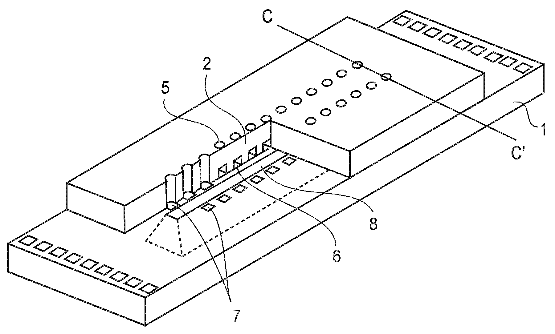
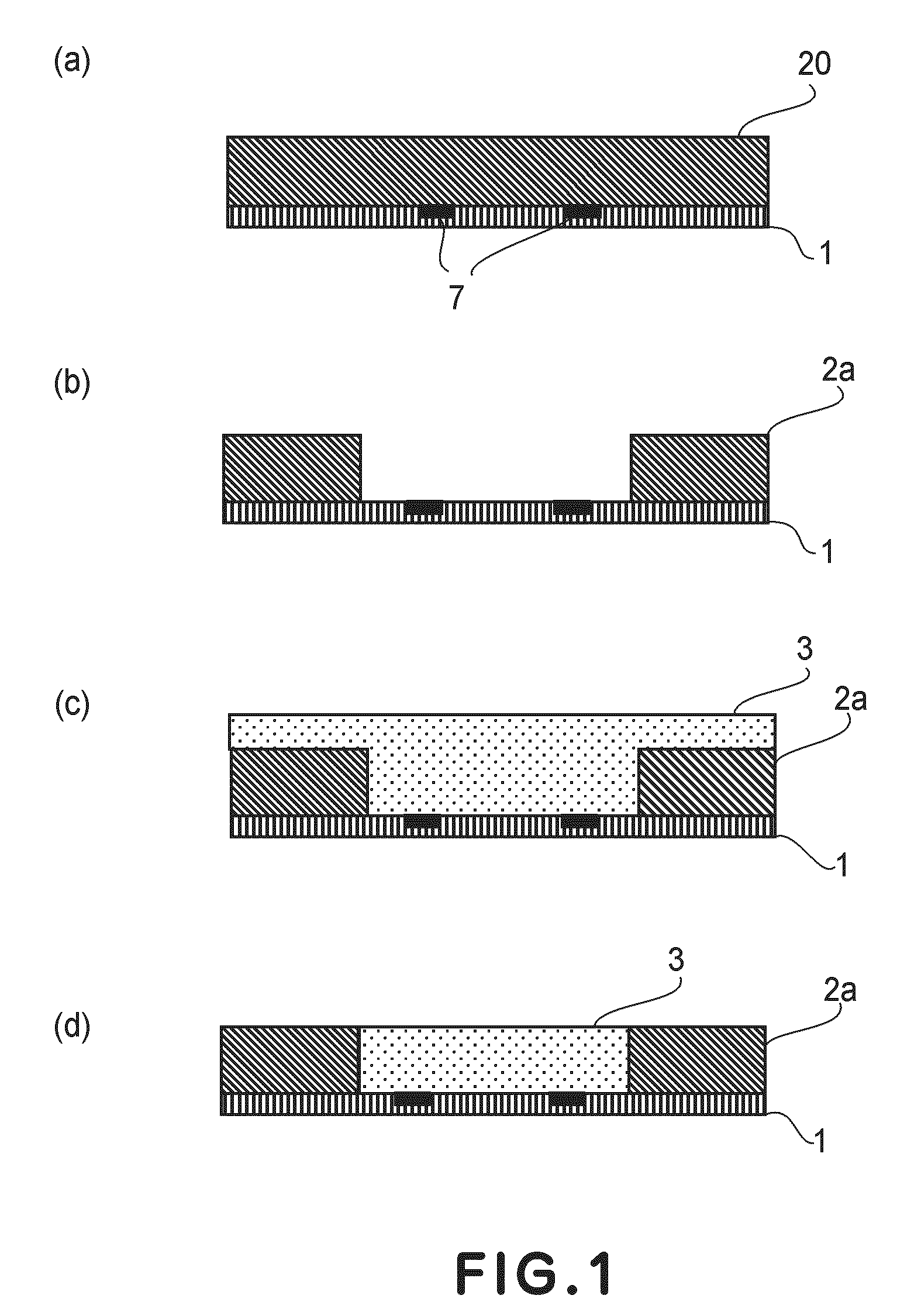
[0070]First, on the substrate 1 provided with heat generating resistors 7 as an energy generating element, a negative photosensitive resin material consisting of Composition 1 shown below was spin-coated in a thickness of 10 μm, followed by pre-baking on a hot plate at 90° C. for 3 minutes to form a negative photosensitive resin layer 20 (FIG. 1(a)).
[0071]
Epoxy resin (“EHPE”, mfd. by DAICEL CHEMICAL100 wt. partsINDUSTRIES, LTD.)Additive (“1,4-HFAB”, mfd. by Central Glass Co., 20 wt. partsLtd.)Photo-cation polymerization initiator (“SP-170”, 2 wt. partsmfd. by ADEKA CORPORATION)Catalyst (“A-187”, mfd. by Nippon Unicar Co., 5 wt. partsLtd.)Solvent (methyl isobutyl ketone)100 wt. partsSolvent (diglyme)100 wt. parts
[0072]Next, the negative photosensitive resin layer 20 was exposed to light of a wavelength of 290-400 nm at an exposure amount of 500 mJ / cm2 by using an aligner (“MPA-600”, mfd. by Canon Kabushiki Kaisha) and then was subject to PEB (post exposure bake) at 90° C. for 4 minut...
embodiment 2
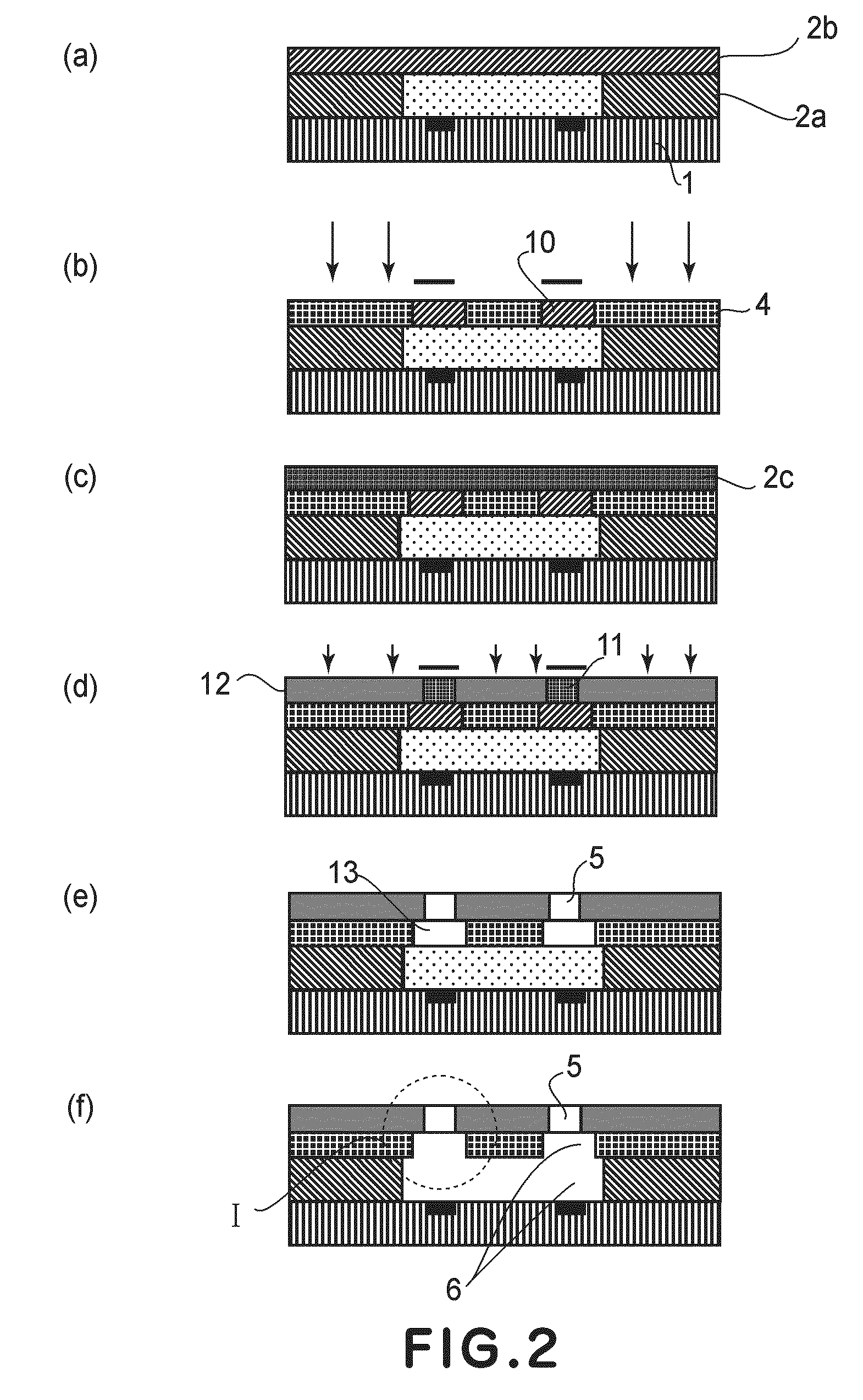
[0085]Until the step shown in FIG. 2(a), the manufacturing method of the recording head was performed in the same manner as in Embodiment 1.
[0086]Then, on the first layer 2b, the second layer 2c was formed of Composition 2 by spin coating, followed by pre-baking (FIG. 6(a)).
[0087]Next, the first layer 2b was exposed to the light of the wavelength of 290-400 nm, followed by baking to form a cured portion 4 as a part of a flow passage-forming member (FIG. 6(b)).
[0088]Next, the second layer 2c was exposed to the light of the wavelength of 365 nm, followed by baking to form a cured portion 12 as an ejection outlet-forming member (FIG. 2(d)).
[0089]Thereafter, the manufacturing method was carried out in the same manner as in Embodiment 1.
[0090]In this embodiment, the first layer 2b has a low photosensitivity to the light of the wavelength of 365 nm used for exposing the second layer 2c, so that an unexposed portion 10 of the first layer 2b is not photosensitive to the light. Therefore, it...
embodiment 3
[0091]A manufacturing method of a recording head will be described with reference to FIGS. 3(a) to 3(c) which are schematic sectional views similar to FIGS. 1(a) to 1(d).
[0092]Until the step shown in FIG. 2(a), the manufacturing method was performed in the same manner as in Embodiment 1.
[0093]Next, a negative photosensitive resin layer having low photosensitivity was formed as the first layer 2b in a thickness of 3 μm by spin coating and then a negative photosensitive resin layer having high photosensitivity was formed as the second layer 2c in a thickness of 10 μm by spin coating.
[0094]The first layer 2b was formed of the following photocurable composition.
EHPE-3150 (cation-polymerizable compound) (trade50wt. partsname, mfd. by DAICEL CHEMICAL INDUSTRIES,LTD.)SP-172 (photo-cation polymerization initiator)1wt. part(trade name, mfd. by ADEKA CORPORATION)A-187 (silanecoupling agent) (trade name, mfd. by2.5wt. partsNippon Unicar Co., Ltd.)
[0095]To these ingredients, triethanol amine (...
PUM
Abstract
A manufacturing method of a liquid ejection head including an ejection outlet forming member provided with an ejection outlet for ejecting liquid and a flow passage communicating with the ejection outlet is constituted by the steps of: preparing a substrate on which a flow passage wall forming member for forming a part of a wall of the flow passage and a solid layer having a shape of a part of the flow passage contact each other, wherein the flow passage wall forming member has a height, from a surface of the substrate, substantially equal to that of the solid layer; providing a first layer, on the solid layer and the flow passage wall forming member, formed of a negative photosensitive resin material for forming another part of the wall of the flow passage; exposing to light a portion of the first layer correspondingly to the another part of the wall of the flow passage; providing a second layer, on the exposed first layer, formed of a negative photosensitive resin material to constitute the ejection outlet forming member; exposing to light a portion of the second layer correspondingly to the ejection outlet forming member; and forming the ejection outlet and another part of the flow passage by removing unexposed portions of the first layer and the second layer.
Description
FIELD OF THE INVENTION AND RELATED ART[0001]The present invention relates to a manufacturing method of a liquid ejection head for ejecting liquid. Specifically, the present invention relates to a manufacturing method of an ink jet recording head in which recording is carried out by ejecting ink onto a recording medium.[0002]An example of using a liquid ejection head for ejecting liquid includes an ink jet recording head used in an ink jet recording method.[0003]The ink jet recording head generally includes a flow passage, energy generating elements provided at a part of the flow passage, and minute ink ejection outlets for ejecting ink (also called “orifice”).[0004]As a method of manufacturing such an ink jet recording head, U.S. Pat. No. 4,657,631 discloses the following manufacturing method. That is, a mold for the flow passage is formed of a photosensitive resin material on a substrate on which the energy generating elements are formed and then a coating resin material layer is f...
Claims
Application Information
Patent Timeline
Application Date:The date an application was filed.
Publication Date:The date a patent or application was officially published.
First Publication Date:The earliest publication date of a patent with the same application number.
Issue Date:Publication date of the patent grant document.
PCT Entry Date:The Entry date of PCT National Phase.
Estimated Expiry Date:The statutory expiry date of a patent right according to the Patent Law, and it is the longest term of protection that the patent right can achieve without the termination of the patent right due to other reasons(Term extension factor has been taken into account ).
Invalid Date:Actual expiry date is based on effective date or publication date of legal transaction data of invalid patent.

