Eureka AIR delivers breakthrough ideas for toughest innovation challenges, trusted by R&D personnel around the world.

Method for preparing a ring-formed body, and magnetic memory device and method for manufacturing the same

Inactive Publication Date: 2006-09-19
SONY CORP
View PDF4 Cites 6 Cited by
  • Summary
  • Abstract
  • Description
  • Claims
  • Application Information

AI Technical Summary

Benefits of technology

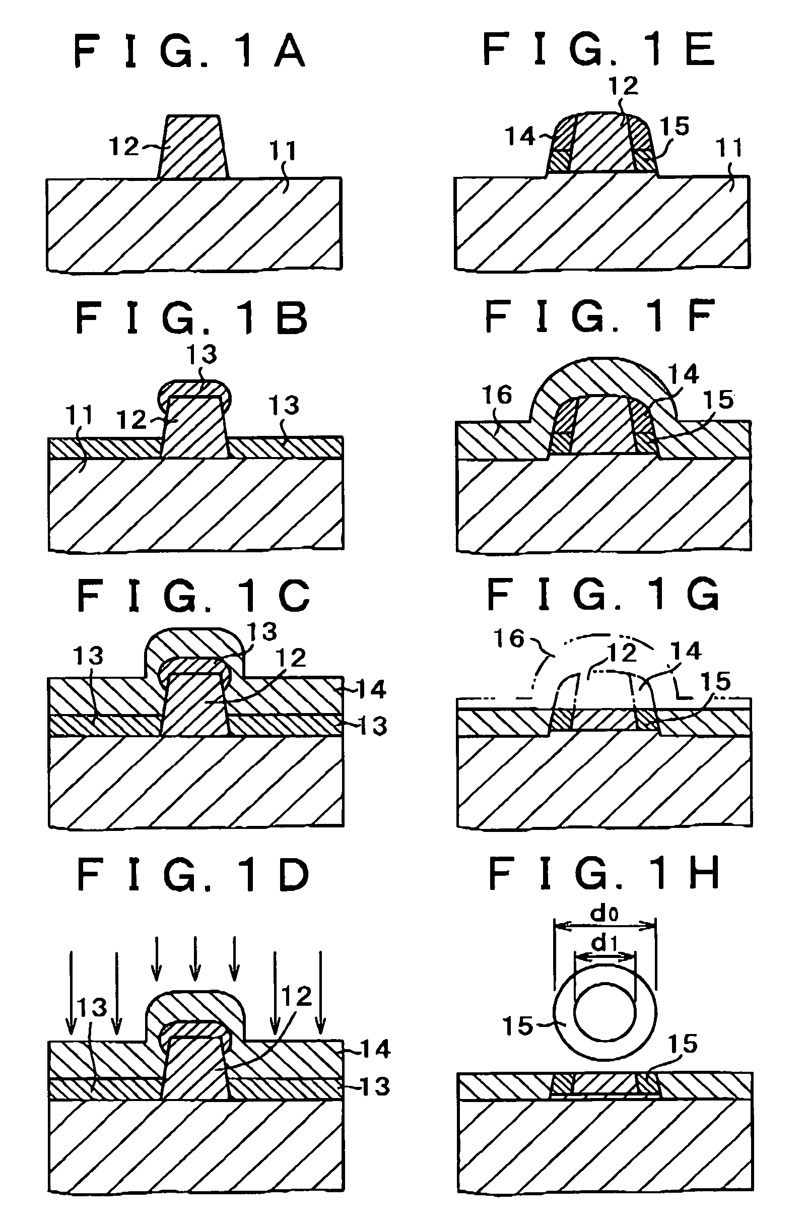
[0018]In the method for preparing a ring-formed body, the ring-formed body forming film is deposited using the column as a core, and the mask film for covering the ring-formed body forming film is formed and then the mask film and the ring-formed body forming film are subjected to anisotropic processing, and hence the ring-formed body is formed by so-called self-coordination. Therefore, a very small ring-formed body having a submicron size (diameter) or less and having a thickness in the order of nm to Å can be formed with high accuracy and high reproducibility. The column is formed and then the ring-formed body forming film is deposited on the periphery of the column, and therefore an unnecessary film is not deposited on the inside of the ring-formed body.
[0020]By appropriately changing the form of the column, the inner and outer diameters and thickness of the ring-formed body can be controlled arbitrarily with high accuracy. Therefore, the ring-formed body formed can have a consistent size.
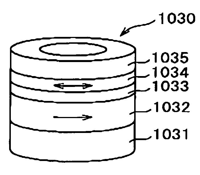
[0021]When the conductive material in a columnar form and the nonmagnetic material film formed on the sidewall of the conductive material constitute the column, the ring-formed body having the conductive material extending along the center portion can be formed. When the ring-formed body having the conductive material (e.g., current line) extending along the center portion is formed from a multilayer film comprising a magnetic layer and used as a memory cell, a current is allowed to flow the conductive material to generate a current magnetic field in the circumferential direction of the ring-formed body, enabling inversion of magnetization of the memory cell. The conductive material extends along the center of the ring-formed body and the ring-formed body is formed to be extremely close to the periphery of the conductive material, and therefore the current magnetic field having a high intensity in the circumferential direction can be efficiently utilized. Further, the ring-formed body itself serves as a magnetic shield, and hence there is an advantage in that the effect of magnetic field leakage on the adjacent element can be removed.
[0023]In the magnetic memory device, inversion of the direction of magnetization of one magnetic layer as a free layer can be achieved merely by means of a current without a magnetic field. Therefore, the magnetic memory device can be applied to writing on the memory layer in a magnetic memory, such as an MRAM. In addition, when putting the magnetic memory device of the present invention into practical use, for meeting the demands of the memory cell having a single magnetic domain and lowering of the current at inversion, the cell size can be as small as about 200 nm or less, so that the demands of an increase of the memory capacity can be satisfied. Further, the smaller the memory cell, the smaller the current required for the inversion. Therefore, readout and writing can be achieved only by a sense current. For example, readout can be performed by a small current and writing can be performed by a large current. Further, there is no semi-selection state in the current magnetic field writing, and therefore the magnetic memory device is thermally stable. In other words, the magnetic memory device has an advantage in that the resistance to thermal fluctuation is high. In addition, the structure of the memory element is considerably simplified, and a word line for writing needed in a conventional MRAM is not required and a by-pass line is not needed, and further the memory element can be arranged immediately above, for example, an FET which serves as an element for selection. Accordingly, the magnetic memory device is advantageously used as a constituent of a large scale integrated circuit.
[0025]By the method for manufacturing a magnetic memory device, the magnetic memory device of the present invention can be easily produced. Specifically, the ring-formed magnetic memory element is formed employing the method for preparing a ring-formed body of the present invention, and therefore the ring-formed magnetic memory element can be easily produced from a ring-formed stacked film comprising a magnetic layer, a nonmagnetic layer, and a magnetic layer with high accuracy and high reproducibility.

Problems solved by technology

However, when the distance between the memory cells is smaller, a problem arises in that magnetic field leakage occurs from the memory cell comprised of a magnetic material to the adjacent memory cell.
However, it is difficult to produce with high accuracy and high reproducibility a ring-formed film which is of a size in the order of submicron and very thin, and one which can be practically used has not yet been produced.
However, in the method for preparing a ring-formed magnetic film recently reported by Nakatani et al., a film is deposited utilizing the shade of the wall of the hole, and therefore diffraction of the flying sputtering particles inevitably occurs to cause a thin film to be deposited on the inside of the ring.
In addition, the film is deposited on the inner wall of the hole and therefore, when a multilayer film is formed, the interface between films cannot be parallel to the substrate, thus causing mixing in the side of the multilayer film.
For this reason, this method is limited to formation of a ring comprised of a single layer film.
Further, in this method, control of the height (thickness) of the ring is difficult and therefore, it is difficult to form with high accuracy a ring-formed body having a thickness in the order of several nm which is required from a practical point of view when the ring-formed body is applied to a magnetic memory device.
However, positioning for forming a hole in the center portion of a number of very small circular disks is extremely difficult and is not practical.

Method used


Image

  • Method for preparing a ring-formed body, and magnetic memory device and method for manufacturing the same
  • Method for preparing a ring-formed body, and magnetic memory device and method for manufacturing the same
  • Method for preparing a ring-formed body, and magnetic memory device and method for manufacturing the same

Examples


first embodiment

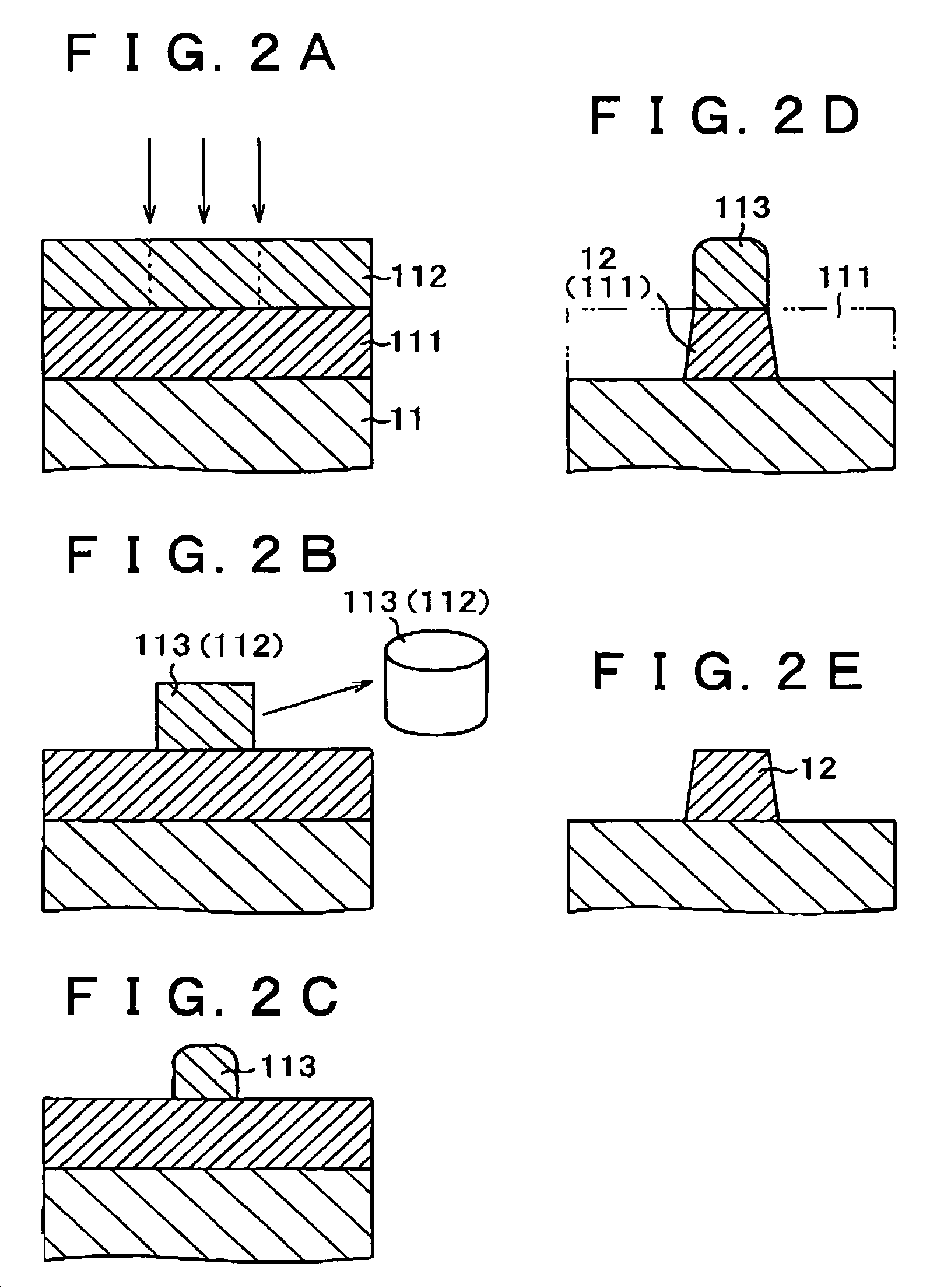
[0038]The method for preparing a ring-formed body according to the present invention will be described with reference to the diagrammatic views of steps of FIGS. 1A to 2E. The method for preparing a ring-formed body of the present invention for a ring-formed body comprised of a single layer film is similar to that for a ring-formed body comprised of the below-described multilayer film. Therefore, FIGS. 1A to 1H illustrate a method for the ring-formed body comprised of a single layer film, and the method for preparing a ring-formed body comprised of a single layer film is described below. FIGS. 2A to 2E illustrate a method for producing a column.

[0039]As shown in FIG. 1A, on a substrate 11, a column 12 in a columnar form which serves as a core of a ring-formed body is formed.

[0040]The method for preparing the column 12 is described with reference to FIGS. 2A to 2E. The values used in the description below are merely examples when forming the column for the purpose of forming a ring-f...

second embodiment

[0055]Next, the method for preparing a ring-formed body according to the present invention will be described with reference to the diagrammatic cross-sectional view of FIG. 4. The method for preparing a ring-formed body of the present invention is for a ring-formed body comprised of a multilayer film.

[0056]The steps for forming a ring-formed body comprised of a multilayer film are basically the same as the steps in the first embodiment. The step in which the ring-formed body forming film 13 is formed from a multilayer film is different from the first embodiment.

[0057]In the present embodiment, as the ring-formed body forming film 13 which is advantageously used in, for example, a magnetic random access memory (hereinafter, frequently referred to simply as “MRAM”), a multilayer film having a magnetic tunnel junction (hereinafter, frequently referred to simply as “MTJ”) which exhibits a tunnel magnetoresistance (hereinafter, frequently referred to simply as “TMR”) effect is used. The ...

third embodiment

[0060]Next, the method for preparing a ring-formed body according to the present invention will be described with reference to the diagrammatic views of steps of FIGS. 5A to 5G. The method for preparing a ring-formed body of the present invention is a method for the case where a conductive material is formed in the center of the ring-formed body.

[0061]The present third embodiment is basically the same as the first embodiment. The method for forming the column 12 is different from that in the first embodiment, The method for forming the column 12 is mainly described below.

[0062]As shown in FIG. 5A, on a substrate 11 having an arbitrary circuit formed thereon, a resist film 211 for lithography is formed by, for example, application. The resist film 211 has a thickness of, for example, 100 to 200 nm. As the resist film 211, a resist film for electron beam lithography is used. The resist for electron beam lithography used is of a positive type such that the portion irradiated with an el...


PUM


Abstract

A method of preparing a ring-formed body comprises the steps of: forming, on a substrate, a column in a columnar form which serves as a core of a ring-formed body; depositing, on both the substrate and the column, a ring-formed body forming film for forming the ring-formed body so that the ring-formed body forming film formed on the substrate and that formed on the column are separated from each other; forming a mask film for covering the ring-formed body forming film; and subjecting the mask film and ring-formed body forming film to anisotropic dry etching so that the films remain on a sidewall of the column, forming a ring-formed body comprised of the ring-formed body forming film having the mask film.

Description

CROSS REFERENCE TO RELATED APPLICATION[0001]This application claims priority from Japanese Priority Document No. 2003-048614, filed on Feb. 26, 2003 with the Japanese Patent Office, which document is hereby incorporated by reference.BACKGROUND OF THE INVENTION[0002]1. Field of the Invention[0003]The present invention relates to a method for preparing a ring-formed body, and a magnetic memory device and a method for manufacturing the same. More particularly, the present invention is concerned with a method for preparing a ring-formed body used for forming a ring-formed magnetic memory element, a magnetic memory device comprising a magnetic memory element comprised of the ring-formed body, and a method for manufacturing the magnetic memory device.[0004]2. Description of Related Art[0005]A magnetic memory device, such as a magnetoresistance effect type random access memory (MRAM), stores information (“0” or “1”) in a memory element utilizing the direction of magnetization of a very sma...

Claims


Application Information

Patent Timeline
IPC IPC(8): H01L21/00G11C11/15H01L21/8236H01L21/8246H01L27/105H01L27/22H01L31/20H01L43/08H01L43/12
CPCB82Y10/00H01L43/12H01L43/08H01L27/228H10B61/22H10N50/01H10N50/10
Inventor YAGAMI, KOJIROMOTOYOSHI, MAKOTO
Owner SONY CORP
Why Eureka
Eureka Blog
Learn More