Segment type color wheel and manufacturing method of same

a color wheel and segment technology, applied in the field of segment type color wheel and manufacturing method of same, can solve the problems of unwanted burrs, achieve the effect of reducing the amount of spherical spherical spherical spherical spherical spherical spherical spherical spherical spherical spherical spherical spherical spherical

Inactive Publication Date: 2008-07-15
MINEBEA CO LTD
View PDF37 Cites 0 Cited by
  • Summary
  • Abstract
  • Description
  • Claims
  • Application Information

AI Technical Summary

Benefits of technology

[0011]The present invention has been made in the light of the above problem, and it is an object of the present invention to provide a segment type color wheel, in which a spoke generated between adjacent color filter segments is minimized in dimension without increase in production cost.
[0012]In order to achieve the object described above, according to a first aspect of the present invention, a color wheel is provided, which includes: a plurality of color filter segments disposed so as to form a disk configuration, each of the color filter segments including an outer circumference configured circular, an inner circumference having a shorter dimension than the outer circumference, and two sides each connecting between the outer circumference and the inner circumference, wherein a chamfer is provided at the innermost portion of at least one of the two sides; and a support member to fixedly set the plurality of color filter segments in place. The chamfer thus provided generates a clearance between opposing sides of any two adjacent color filter segments, so as to house burrs that are often formed at the sides, and therefore the opposing sides are fitted closely to each other even when burrs are formed at the sides. Consequently, spokes generated between two adjacent color filter segments can be minimized.
[0013]In the first aspect of the present invention, the inner circumference may be straight, or alternatively be circular such that the center point of a circle defined by the inner circumference of each color filter segment is located farther from the color filter segment than the center point of a circle defined by the outer circumference of the color filter segment. In whichever case, the inner circumference can be processed with enhanced workability.
[0015]According to a second aspect of the present invention, there is provided a method of manufacturing a color wheel which includes a plurality of color filter segments disposed so as to form a disk configuration, and a support member to fixedly set the plurality of color filter segments in place. The method includes the steps of processing each of the color filter segments so as to include an outer circumference configured circular, an inner circumference having a shorter dimension than the outer circumference, and two sides each connecting between the outer circumference and the inner circumference; and forming a chamfer at the innermost portion of at least one of the two sides. The chamfer thus formed generates a clearance between opposing sides of any two adjacent color filter segments, so as to house burrs that are often formed at the sides, and therefore the opposing sides are fitted closely to each other even when burrs are formed at the sides. Consequently, spokes generated between two adjacent color filter segments can be minimized.
[0016]In the second aspect of the present invention, the inner circumference may be shaped straight, or alternatively circular such that a center point of a circle defined by the inner circumference of each color filter segment is located farther from the color filter segment than a center point of a circle defined by the outer circumference of the color filter segment. In whichever case, the inner circumference can be processed with enhanced workability.
[0018]Accordingly, a segment type color wheel can be provided, in which spokes formed between two adjacent color filter segments are minimized thus enhancing the quality without production cost increase.

Problems solved by technology

When a color filter segment is carved out of a glass substrate scribed by a scriber, burrs may be unwantedly formed.

Method used


Image

  • Segment type color wheel and manufacturing method of same
  • Segment type color wheel and manufacturing method of same
  • Segment type color wheel and manufacturing method of same

Examples


Embodiment Construction

[0029]Preferred embodiments of the present invention will hereinafter be described with reference to the accompanying drawings.

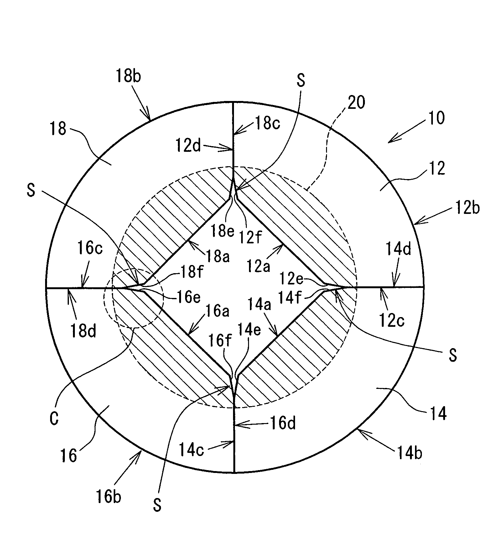
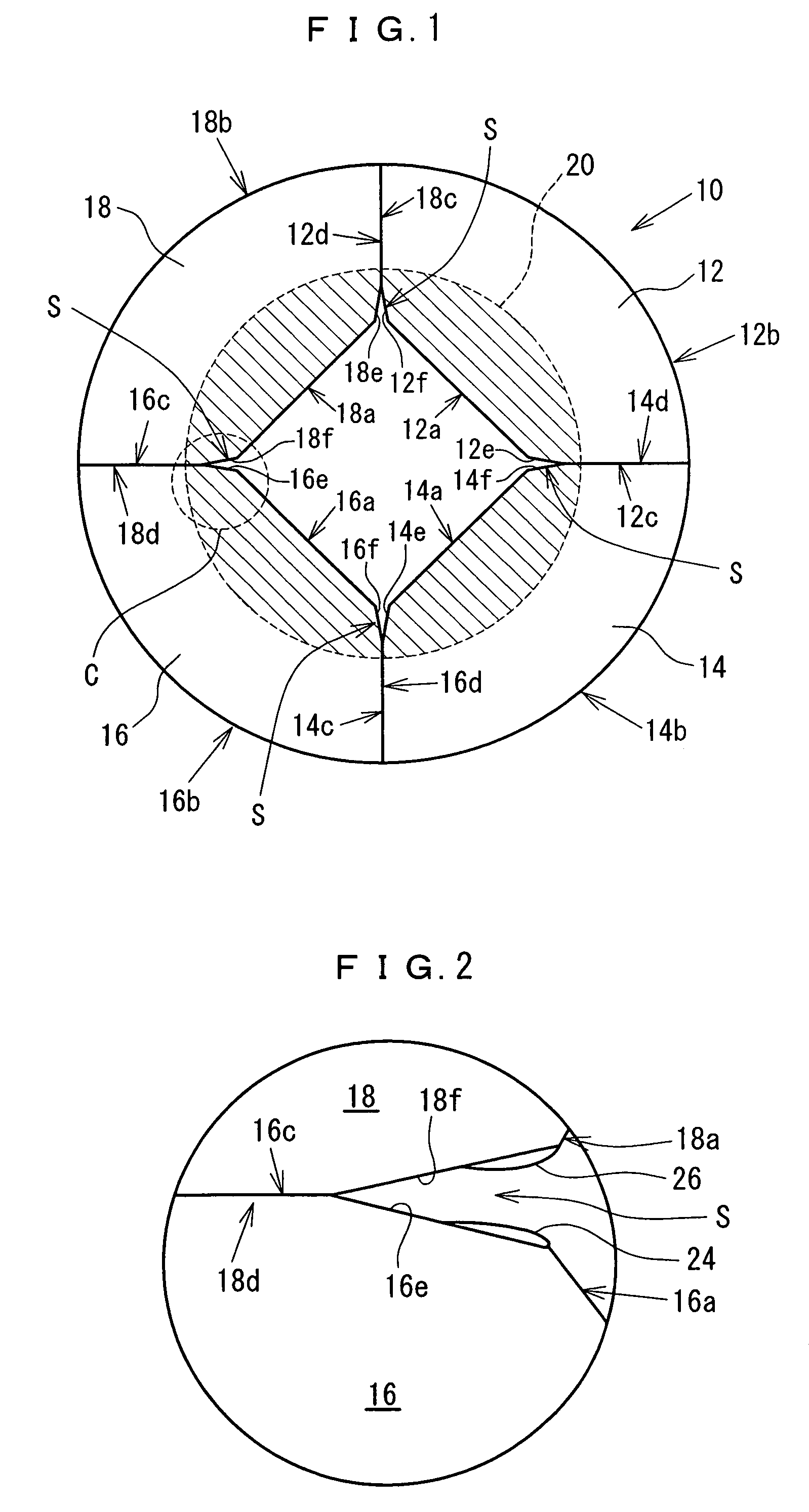
[0030]A first embodiment of the present invention will be described with reference to FIGS. 1 and 2. Referring to FIG. 1, a segment type color wheel 10 according to the first embodiment includes a plurality (four in the present embodiment) of color filter segments 12, 14, 16 and 18, and a support member 20. The color filter segments 12, 14, 16 and 18 have respective outer circumferences 12b, 14b, 16b and 18b defined circular, respective inner circumferences 12a, 14a, 16a and 18a measuring shorter than the respective outer circumferences 12b, 14b, 16b and 18b, and respective both sides 12c / 12d, 14c / 14s, 16c / 16d and 18c / 18d each connecting between the outer circumference and the inner circumference, and are fixedly set in place by means of the support member 20 so as to form a disk in combination, such that the support member 20 covers the shaded areas of the ...


PUM


Abstract

A color wheel includes a plurality of color filter segments disposed so as to form a disk configuration, and a support member to fixedly set the plurality of color filter segments in place. Each of the color filter segments has a circular outer circumference, an inner circumference measuring shorter than the outer circumference, and two sides each connecting between the outer circumference and the inner circumference. In the color wheel described above, a chamfer is provided at the innermost portion of at least one of the two sides. The chamfer provides a clearance between opposing sides of any two adjacent color filter segments, so as to house burrs that are often formed at the sides, and therefore the opposing sides are fitted closely to each other even when burrs are formed at the sides. Consequently, spokes generated between two adjacent color filter segments can be minimized.

Description

BACKGROUND OF THE INVENTION[0001]1. Field of the Invention[0002]The present invention relates to a segment type color wheel suitable as a filter element of a time-share light dispersing device, and to a manufacturing method of the same.[0003]2. Description of the Related Art[0004]Color composition in a projection-type image display apparatus has conventionally been accomplished commonly by a method, such as: a single-panel method, in which one light valve element adapted to control light amount per pixel thereby creating an image is used to disperse each pixel into red (R), green (G), and blue (B) lights; and a three-panel method, in which three light valve elements dedicated to R, G and B lights, respectively, are used to produce R, G and B images in parallel, and then the three images thus produced are combined. Currently, as a light valve element capable of fast switching, such as a ferroelectric liquid crystal display element or a digital micro mirror device, is increasingly com...

Claims


Application Information

Patent Timeline
Patent Type & Authority Patents(United States)
IPC IPC(8): G03B21/14F21V8/00G02B5/22G02B7/00H04N9/12
CPCG02B26/008G03B27/547H04N9/3141G03B21/204G03B21/2093H04N9/3114G02B7/006G03B21/20
Inventor NIWA, SHINICHITAKAO, KUNIYUKI
Owner MINEBEA CO LTD
Why Eureka
Try Eureka