Methods for use in assessing a flow condition of a fluid

a fluid flow and flow condition technology, applied in the direction of fluid speed measurement, diaphragms, immobilised enzymes, etc., can solve the problems of inability to detect excessive fluid flow from the pump, increased cost and complexity of the portable insulin pump, and increased use costs

Inactive Publication Date: 2008-07-15
THERASENSE
View PDF41 Cites 30 Cited by
  • Summary
  • Abstract
  • Description
  • Claims
  • Application Information

AI Technical Summary

Benefits of technology

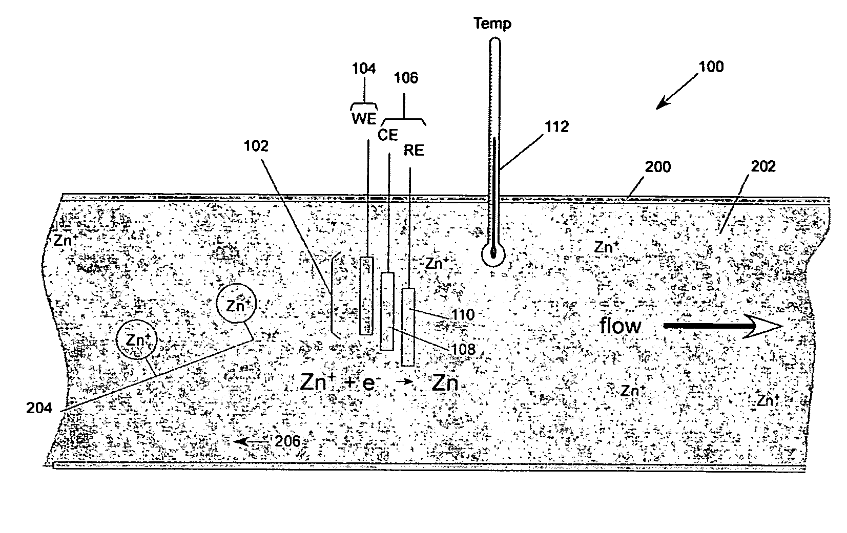
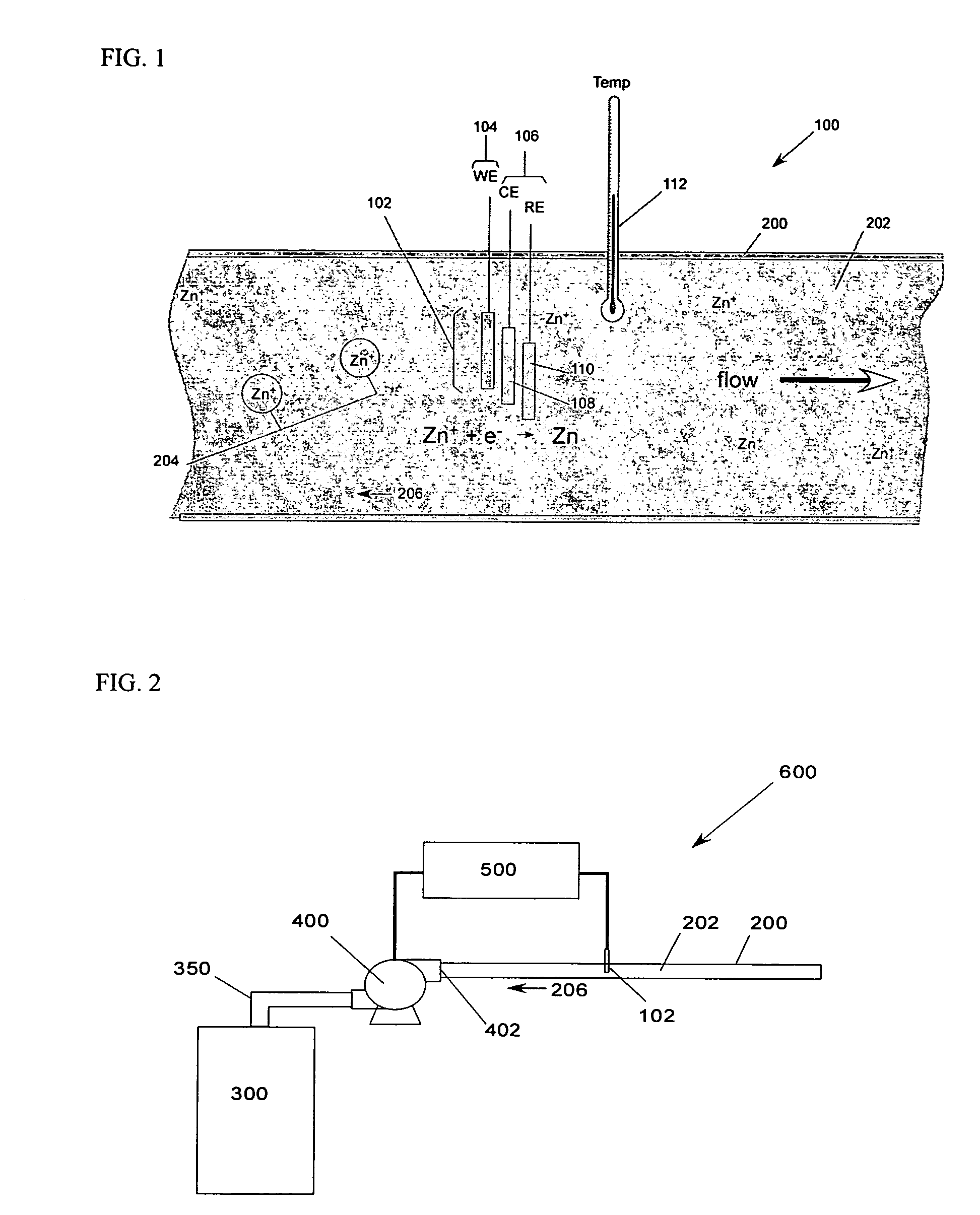
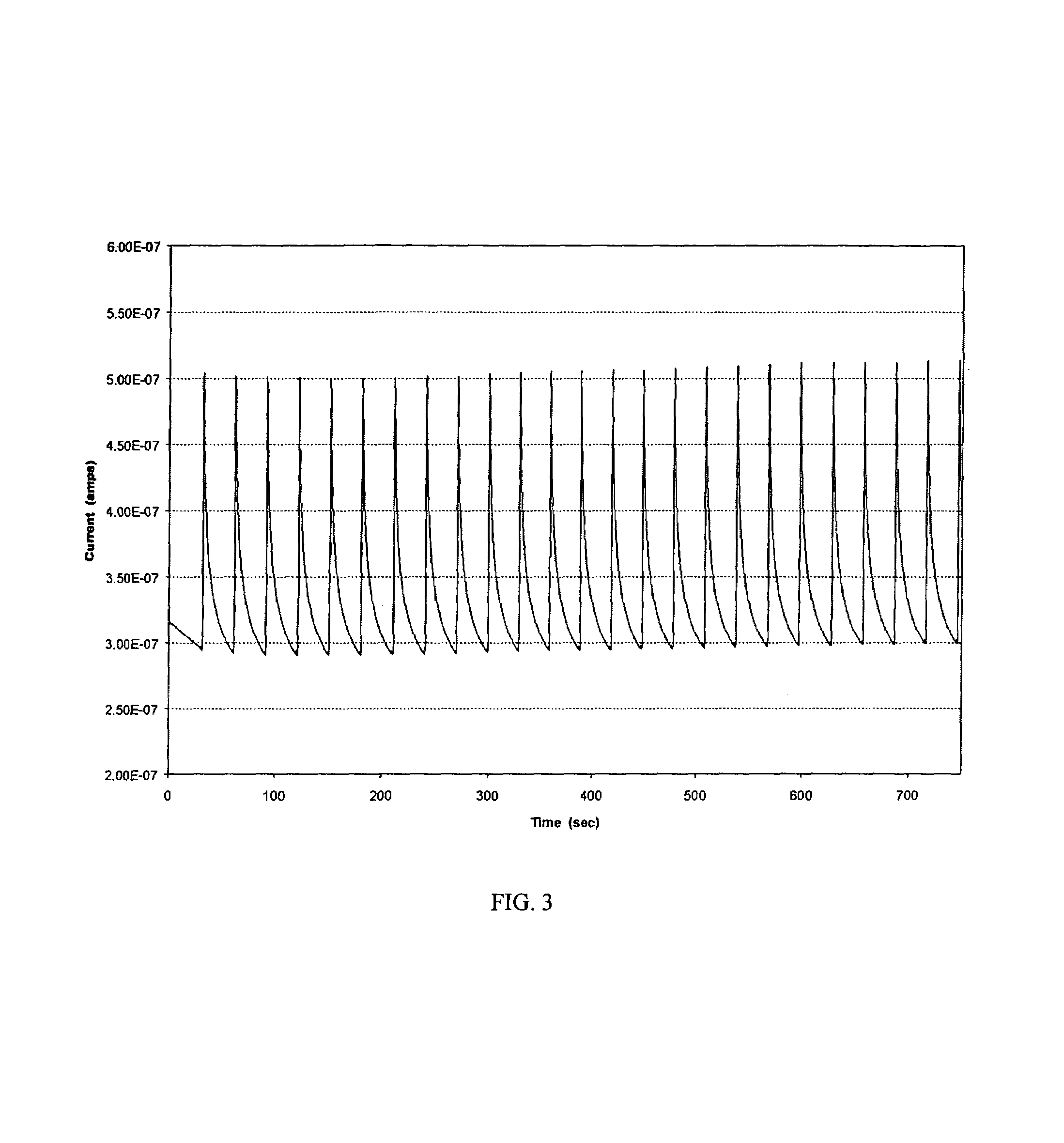
[0011]According to an aspect of the present invention, a technique for assessing, measuring, and / or monitoring flow of a medium is provided. The flow of the medium may be relatively unconfined or natural, such as the flow of water in a body of water, such as sea or ocean water in a body thereof, or may be in a flow path, such as the flow of insulin from an insulin pump through a delivery channel, for example. An electrochemical cell is immersed in the medium and is used to assess, measure, and / or monitor the state of flow of the medium. According to an aspect of the invention, the cell is used to assess, measure, and / or monitor the rate of an electrochemical reaction associated with the medium. According to an aspect of the invention, a device for carrying out the technique is provided. The device may be a simple, inexpensive, qualitative and / or quantitative device.

Problems solved by technology

If these devices fail to deliver a drug to a subject at an acceptable or intended rate, the consequences can be anywhere from relatively minor to relatively major, even deadly.
These means, which include a pressure transducer, can detect insufficient fluid flow from the insulin pump, such as insufficient flow caused by a blockage in the delivery tubing or in the cannula, but cannot detect excessive fluid flow from the pump.
The pressure transducer adds to the cost and complexity of this portable insulin pump.

Method used


Image

  • Methods for use in assessing a flow condition of a fluid
  • Methods for use in assessing a flow condition of a fluid
  • Methods for use in assessing a flow condition of a fluid

Examples


Embodiment Construction

[0023]In the description of the invention herein, it will be understood that a word appearing in the singular encompasses its plural counterpart, and a word appearing in the plural encompasses its singular counterpart, unless implicitly or explicitly understood or stated otherwise. Further, it will be understood that for any given component described herein, any of the possible candidates or alternatives listed for that component, may generally be used individually or in combination with one another, unless implicitly or explicitly understood or stated otherwise. Additionally, it will be understood that any list of such candidates or alternatives, is merely illustrative, not limiting, unless implicitly or explicitly understood or stated otherwise. Still further, it will be understood that any figure or number presented herein in connection with the invention is approximate, and that any numerical range includes the minimum number and the maximum number defining the range, unless imp...


PUM

PropertyMeasurementUnit
areaaaaaaaaaaa
electrode potentialaaaaaaaaaa
timeaaaaaaaaaa

Abstract

A device for use in assessing a flow condition of a fluid, or a fluid in a flow path, is provided. The device comprises at least one electrochemical cell, comprising a working electrode and at least one other electrode, sufficient for communication with the fluid, or sufficient for communication with a flow path, such that when sufficient fluid is in the flow path, the cell is in communication with the fluid. The fluid comprises a component sufficient to affect a mass-transport limited electrochemical reaction at the working electrode. The device also comprises at least one microcontroller operably connected to the at least one electrochemical cell for providing a potential or a current to the working electrode and for assessing the electrochemical reaction. A method of assessing a flow condition of a fluid, or a fluid in a flow path, is also provided. The device and the method of the present invention may be used in connection with the delivery of a fluid-borne or fluidized drug or medicament to a subject.

Description

CROSS REFERENCE TO RELATED APPLICATIONS[0001]The present application is a continuation-in-part of U.S. application Ser. No. 10 / 683,659 of Benjamin M. Rush et al., filed on Oct. 9, 2003, and issued as U.S. Pat. No. 6,916,159 on Jul. 12, 2005, which is related to and claims priority based on U.S. Provisional Application No. 60 / 417,464, entitled “Disposable Pump for Drug Delivery System,” filed on Oct. 9, 2002, and U.S. Provisional Application No. 60 / 424,613, entitled “Disposable Pump and Actuation Circuit for Drug Delivery System,” filed on Nov. 6, 2002, each of which is hereby incorporated herein, in its entirety, by this reference. The parent application, U.S. application Ser. No. 10 / 683,659, was published as U.S. Patent Application Publication No. 2004 / 0115067 A1. The present application is related to U.S. application No. 11 / 106,155 of Benjamin Rush et al., entitled “Variable Volume, Shape Memory Actuated Insulin Dispensing Pump,” published as U.S. Patent Application Publication No...

Claims


Application Information

Patent Timeline
Patent Type & Authority Patents(United States)
IPC IPC(8): G01N27/26G01F1/7088A61M5/142F04B1/00F04B17/00F04B17/04F04B43/04F04B49/06F04B51/00G01N27/416
CPCA61M5/14216G01F25/0007A61M5/16886F04B43/043F04B49/065F04B51/00G01F1/64G01F1/708G01F1/7088A61M5/14244A61M2005/1726A61M2205/0288A61M2205/3317A61M2205/3569A61M2205/3592A61M2205/702F04B2205/09F05C2251/08G01F25/10
Inventor RUSH, BENJAMIN M.
Owner THERASENSE
Why Eureka
Try Eureka