Microfabricated diffusion source

a microfabricated and diffusion source technology, applied in the field of diffusion sources, can solve the problems of affecting the life and affecting the quality of the microfabricated diffusion sour

Active Publication Date: 2008-07-15
NAT TECH & ENG SOLUTIONS OF SANDIA LLC
View PDF11 Cites 20 Cited by
  • Summary
  • Abstract
  • Description
  • Claims
  • Application Information

AI Technical Summary

Problems solved by technology

Quantitative errors can be associated with peak size measurement, standardization, sampling techniques and sample introduction, and chromatographic system errors.
In addition, due to

Method used


Image

  • Microfabricated diffusion source
  • Microfabricated diffusion source
  • Microfabricated diffusion source

Examples


Embodiment Construction

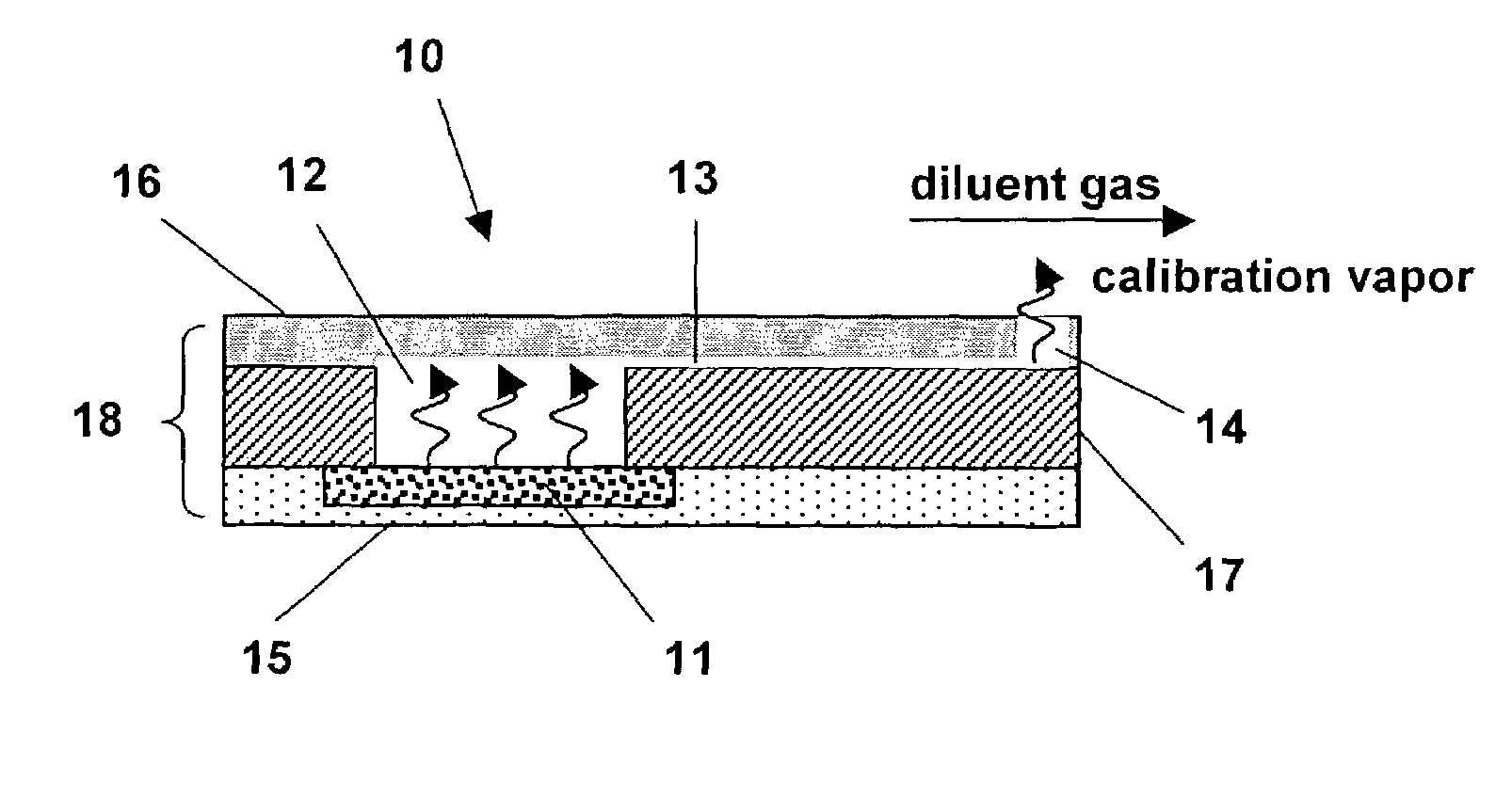
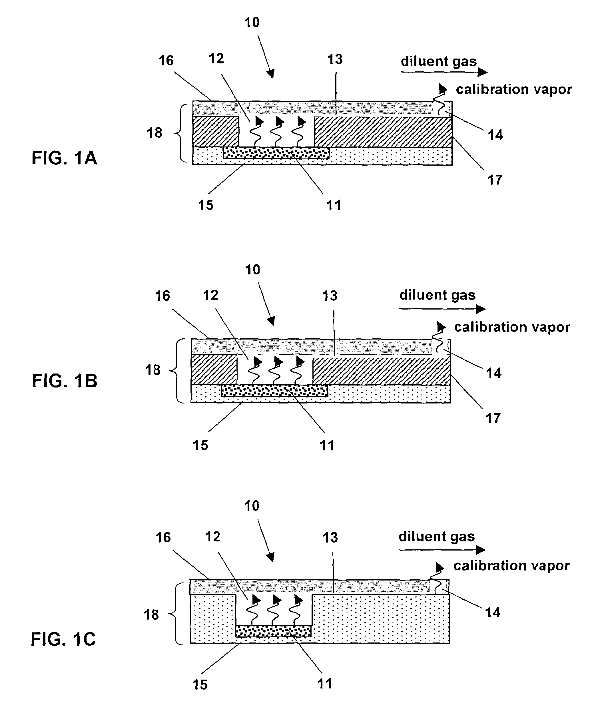
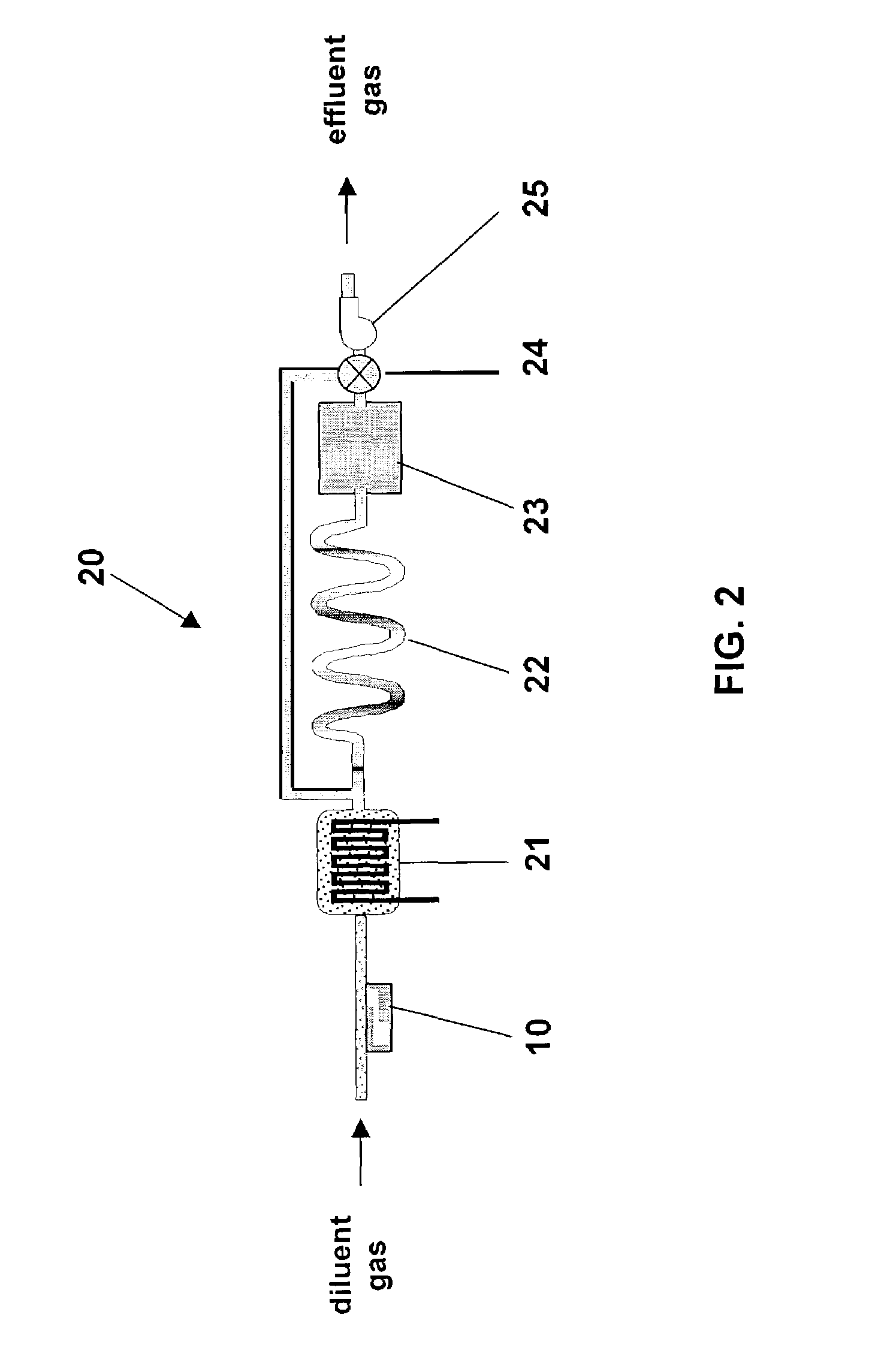
[0019]The present invention comprises a microfabricated diffusion source that can be integrated into a microanalytical system. The microfabricated diffusion source uses the diffusion of vapor from a liquid reservoir through a diffusion channel to add small amounts of the vapor to a flowing diluent gas stream at the sample inlet of the microanalytical system. Furthermore, several diffusion sources of different pure liquids can be placed in the same diluent gas stream to provide multiple vapor standards.

[0020]The concentration of the vapor standard in the flowing gas stream can be determined from

C=RK / F×106  (1)

where C is the vapor standard concentration (ppm), R is the diffusion rate of the vapor (ng / min), K is the reciprocal vapor density of the calibration material (mL / ng), and F is the diluent gas flowrate (mL / min).

[0021]The diffusion rate of the vapor through a diffusion channel in the molecular flow regime is given by

R=2.216×10⁶(DMPA / TL) log [P / (P−Pv)]  (2)

where D is the vapor di...


PUM


Abstract

A microfabricated diffusion source to provide for a controlled diffusion rate of a vapor comprises a porous reservoir formed in a substrate that can be filled with a liquid, a headspace cavity for evaporation of the vapor therein, a diffusion channel to provide a controlled diffusion of the vapor, and an outlet to release the vapor into a gas stream. The microfabricated diffusion source can provide a calibration standard for a microanalytical system. The microanalytical system with an integral diffusion source can be fabricated with microelectromechanical systems technologies.

Description

CROSS-REFERENCE TO RELATED APPLICATION[0001]This application claims the benefit of U.S. Provisional Application No. 60 / 378,035, filed on May 14, 2002.STATEMENT OF GOVERNMENT INTEREST[0002]This invention was made with Government support under contract no. DE-AC04-94AL85000 awarded by the U.S. Department of Energy to Sandia Corporation. The Government has certain rights in the invention.FIELD OF THE INVENTION[0003]The present invention relates to diffusion sources and, more particularly, to a microfabricated diffusion source that can provide precise gas or vapor standards for microanalytical systems.BACKGROUND OF THE INVENTION[0004]For a wide array of analytical techniques, accurate analysis of air or other gas contaminants requires the generation of standard atmospheres to calibrate and verify instrument response. Direct injection of a standard atmosphere into an analytical system can also be used as a diagnostic tool to evaluate the performance of individual system components and th...

Claims


Application Information

Patent Timeline
IPC IPC(8): B01L3/00
CPCG01N33/0006B01L3/5027
Inventor OBORNY, MICHAEL C.FRYE-MASON, GREGORY C.MANGINELL, RONALD P.
Owner NAT TECH & ENG SOLUTIONS OF SANDIA LLC
Why Eureka
Try Eureka