ACM cooling flow path and thrust load design

a technology of thrust load and cooling flow path, which is applied in the direction of positive displacement liquid engine, piston pump, liquid fuel engine, etc., can solve the problems of reducing the life of compressors, hot air from the compressor outlet can leak past the seal between the compressor rotor and the housing,

Active Publication Date: 2008-07-22
HAMILTON SUNDSTRAND CORP
View PDF4 Cites 43 Cited by
  • Summary
  • Abstract
  • Description
  • Claims
  • Application Information

AI Technical Summary

Benefits of technology

[0007]Accordingly, the present invention provides an improved cooling path to address leakage from the compressor and route the leakage around the hydrodynamic thrust bearings.

Problems solved by technology

One problem has been that hot air from the compressor outlet can leak past a seal between the compressor rotor and housing.
The leaked hot compressor air has then flowed through the hydrodynamic thrust bearings, which can reduce their life.

Method used


Image

  • ACM cooling flow path and thrust load design
  • ACM cooling flow path and thrust load design
  • ACM cooling flow path and thrust load design

Examples


Embodiment Construction

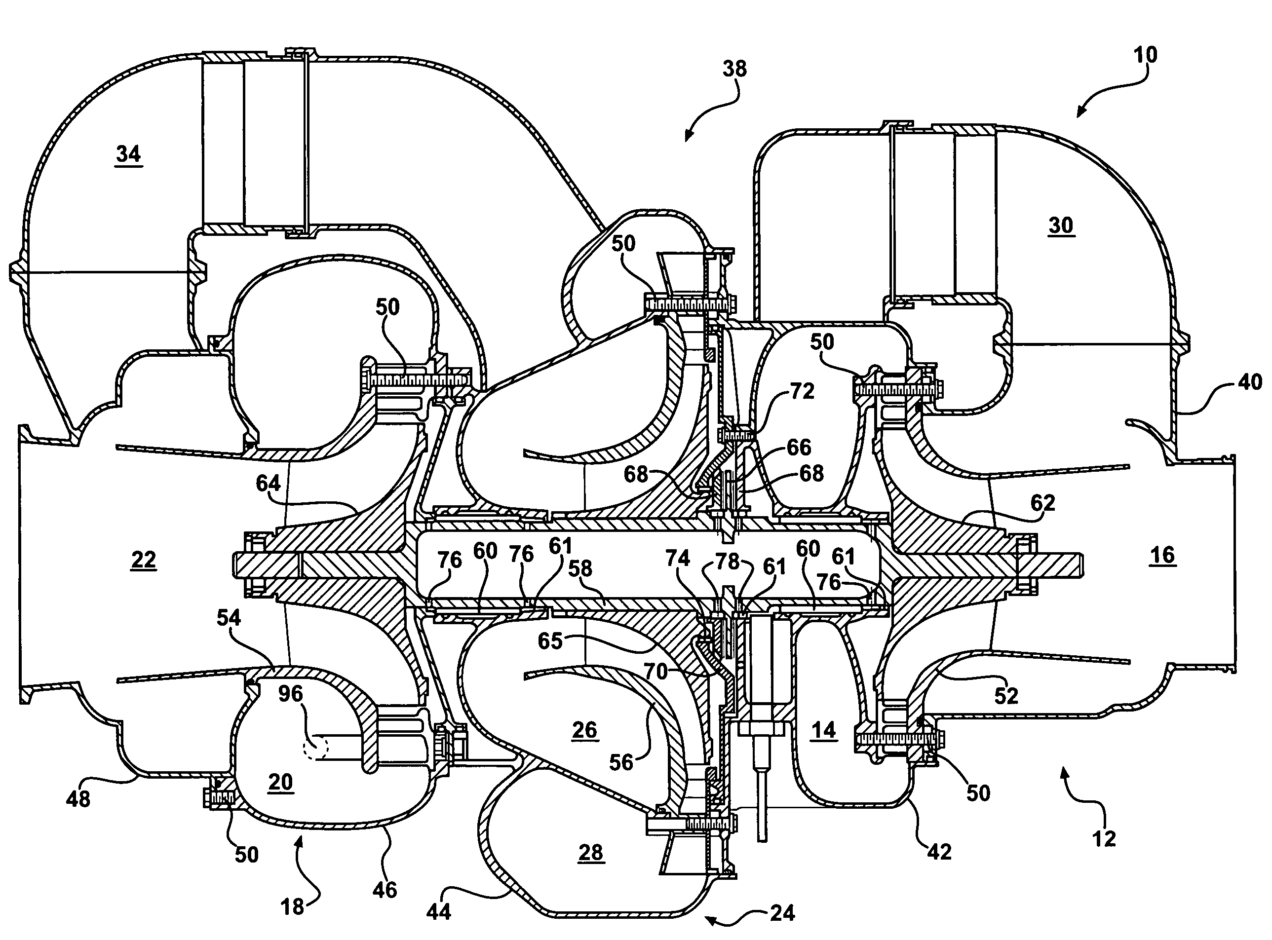
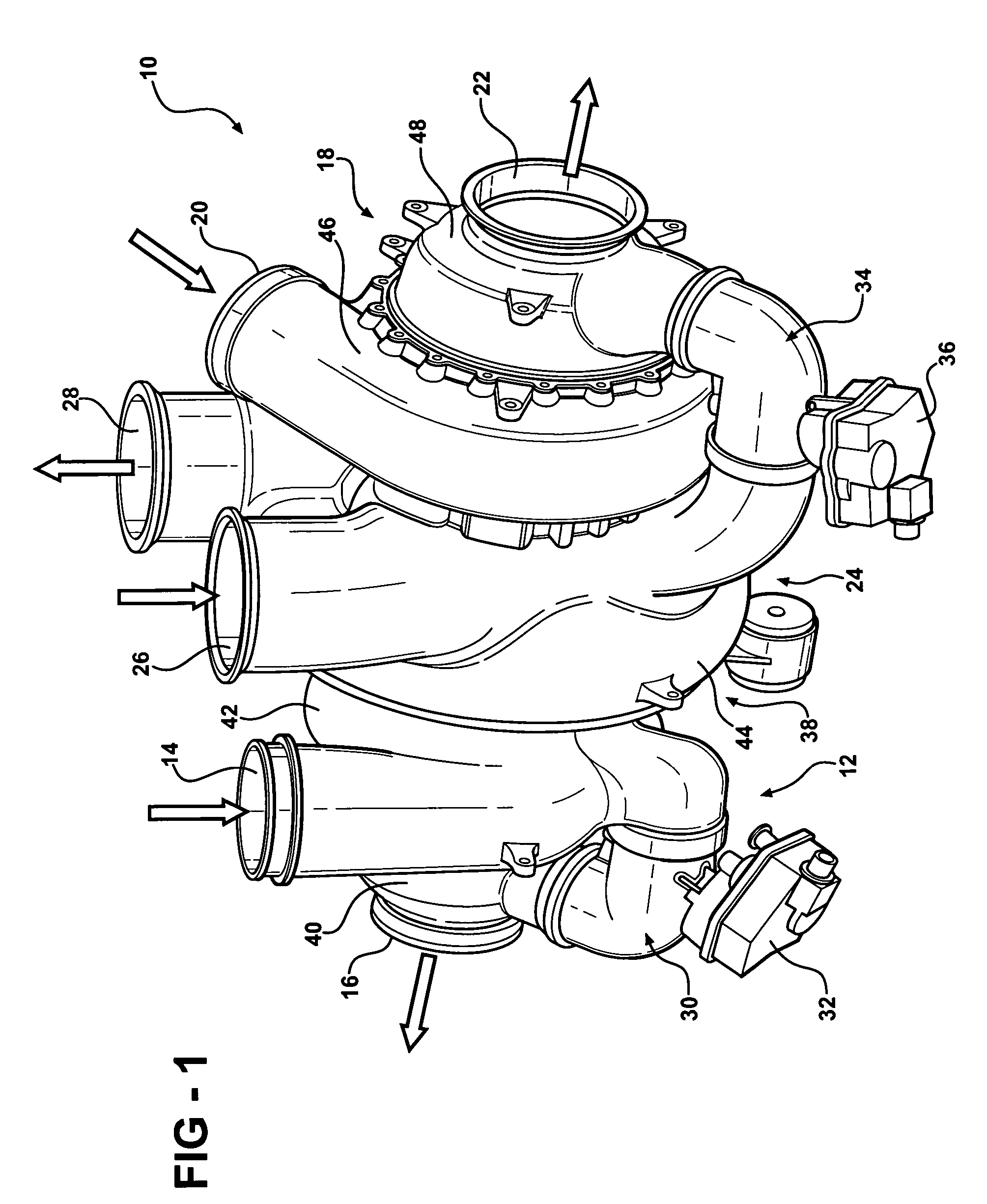
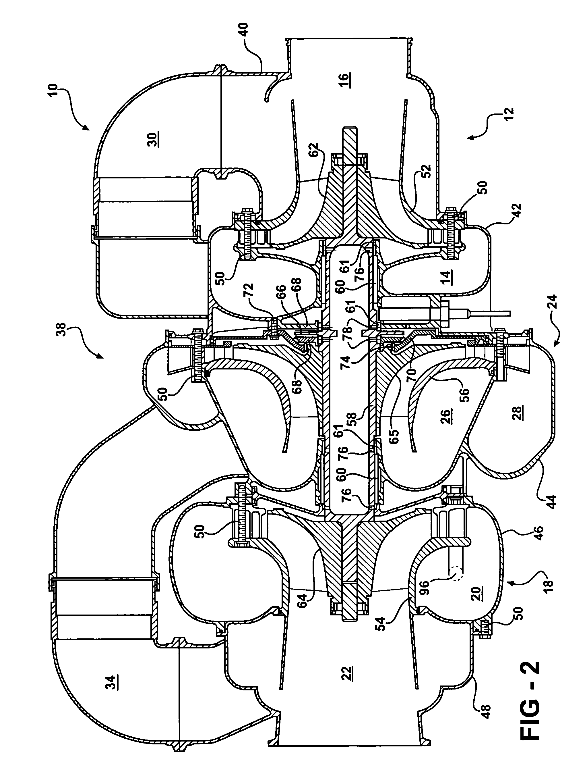
[0013]An air cycle machine (ACM) 10 is shown in FIGS. 1 and 2. The ACM 10 includes a first turbine 12 having an inlet 14 and outlet 16. A second turbine 18 has an inlet 20 and outlet 22. A compressor 24 is driven by the first and second turbines 12 and 18. The compressor 24 includes an inlet 26 and outlet 28. A low limit passage 30 is arranged between the first turbine inlet 14 and outlet 16 with a low limit valve 32 regulating the fluid flow between them. A bypass passage 34 is arranged between the compressor inlet 26 and second turbine outlet 22 with a bypass valve 36 regulating the fluid flow between them.

[0014]The ACM 10 includes first, second, third, fourth, and fifth portions 40, 42, 44, 46 and 48 secured to one another using fasteners 50. The first and second portions 40 and 42 provides a housing for the first turbine 12. The fourth and fifth portions 46 and 48 provide a housing for the second turbine 18. The third portion 44 provides a housing for the compressor 24. The hous...


PUM


Abstract

An air cycle machine includes a housing having a compressor housing portion. A shaft is supported by the housing and includes a thrust runner. A hydrodynamic thrust bearing is arranged adjacent to the thrust runner and includes upstream and downstream sides. A compressor rotor is mounted on the shaft. A seal is arranged between the compressor rotor and the compressor housing portion. An orifice is provided in the compressor housing portion at the downstream side of the hydrodynamic bearing. The orifice vents hot compressed air that may leak past the seal prior to reaching the hydrodynamic thrust bearing.

Description

BACKGROUND OF THE INVENTION[0001]This invention relates to a cooling flow path used for the thrust bearing of an air cycle machine.[0002]One type of air cycle machine uses a radial outflow compressor that is driven by two radial turbines. The compressor and turbines are supported on a common shaft and ride upon hydrodynamic bearings in a housing. A pair of hydrodynamic, foil-type journal bearings support the shaft. The shaft includes a thrust runner. Axial forces imparted on the shaft are counteracted by a pair of thin foil hydrodynamic thrust bearings arranged on either side of the thrust runner.[0003]Various seals are used in the housing to separate the flow into and out of the compressor and turbines seals also help define a cooling path in the housing. Airflow through the cooling path cools the hydrodynamic bearings. One problem has been that hot air from the compressor outlet can leak past a seal between the compressor rotor and housing. The leaked hot compressor air has then f...

Claims


Application Information

Patent Timeline
Patent Type & Authority Patents(United States)
IPC IPC(8): F01D25/16F01D25/12
CPCF04D25/04F04D29/584F04D29/0513F05D2260/6022
Inventor BEERS, CRAIGMCAULIFFE, CHRISTOPHERMERRITT, BRENT
Owner HAMILTON SUNDSTRAND CORP
Why Eureka
Try Eureka