Multiple servo sensor configuration for magnetic tape timing based servo

a timing-based servo and magnetic tape technology, applied in the direction of maintaining head carrier alignment, recording signal processing, instruments, etc., can solve the problem that the error in the longitudinal velocity of the tape cannot be compensated in the magnetic tape drive, and the resultant spacing of the “b” transition cannot be calculated

Inactive Publication Date: 2008-07-22
INT BUSINESS MASCH CORP
View PDF14 Cites 14 Cited by
  • Summary
  • Abstract
  • Description
  • Claims
  • Application Information

AI Technical Summary

Problems solved by technology

Thus substantial error in the velocity of the tape by the servo writer drive or substantial error in the timing between the pulses, results in an error in the “b” distance and hence an error in the lateral position calculated based on the “b” pulse timing.
Thus substantial error in the velocity of the tape by the servo writer drive or substantial error in the timing between the pulses, results in an error in the “b” distance and hence an error in the longitudinal velocity of the tape calculated based on the “b” pulse timing.
Error in the resultant spacing of the “b” transitions cannot be compensated for in the magnetic tape drive because the error is written into the magnetic tape in the servo pattern.

Method used


Image

  • Multiple servo sensor configuration for magnetic tape timing based servo
  • Multiple servo sensor configuration for magnetic tape timing based servo
  • Multiple servo sensor configuration for magnetic tape timing based servo

Examples


Embodiment Construction

[0029]This invention is described in preferred embodiments in the following description with reference to the Figures, in which like numbers represent the same or similar elements. While this invention is described in terms of the best mode for achieving this invention's objectives, it will be appreciated by those skilled in the art that variations may be accomplished in view of these teachings without deviating from the spirit or scope of the invention.

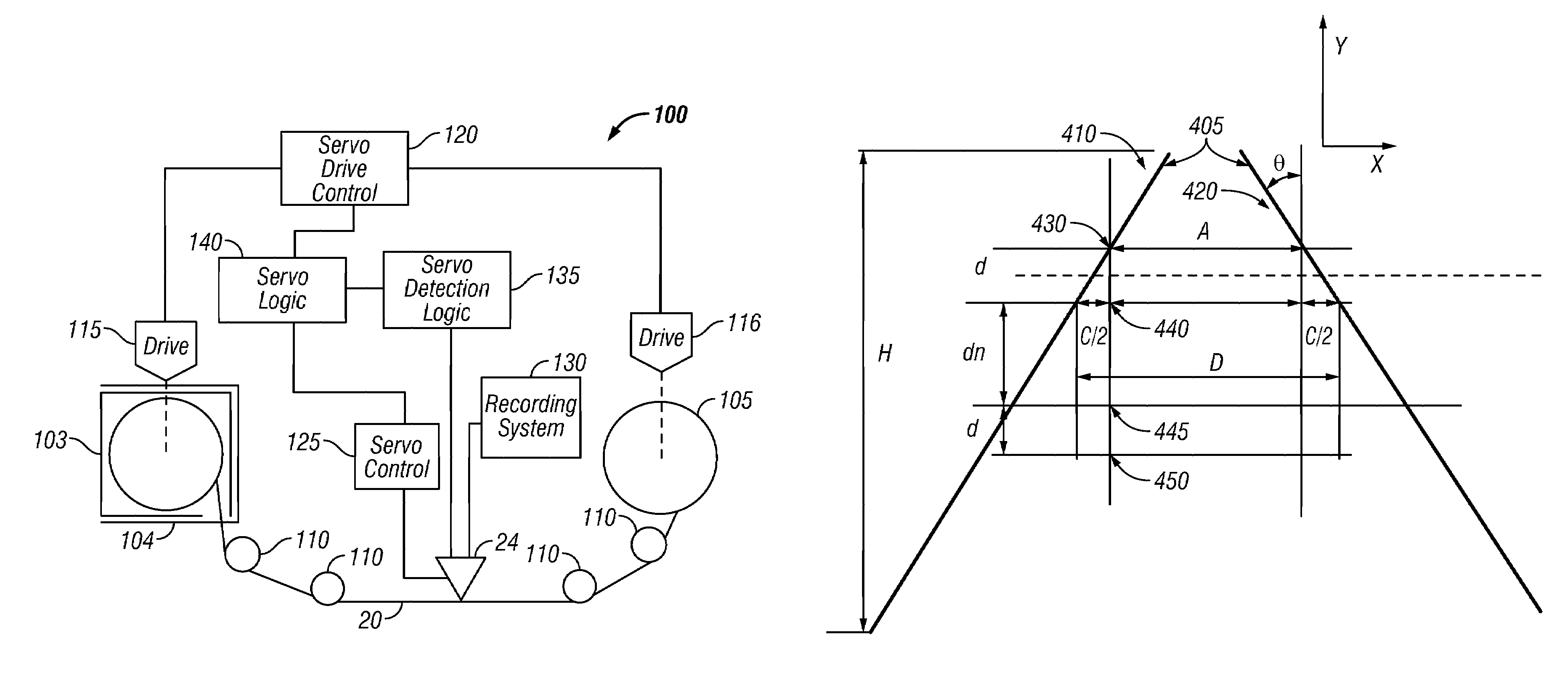
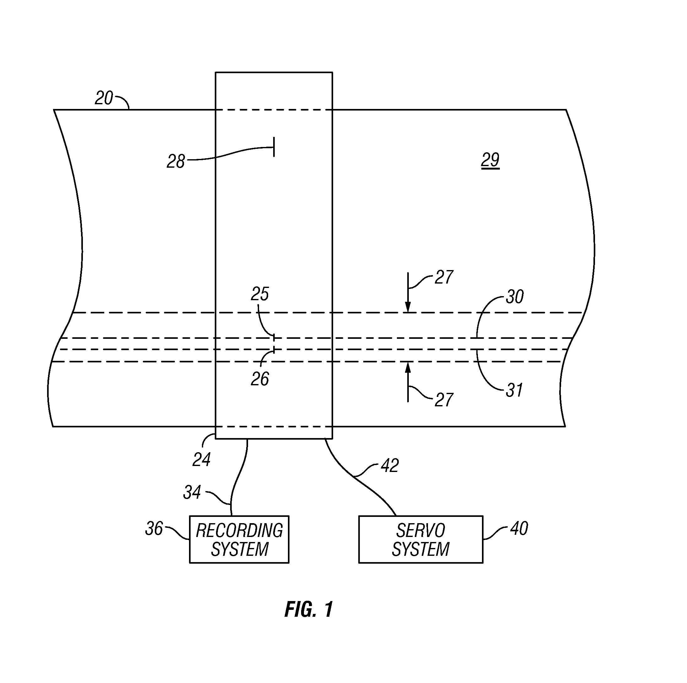
[0030]Referring to FIG. 1, magnetic tape, such as magnetic tape 20 provides a means for storing data which is enhanced by maximizing the amount of data that is stored in a given length of tape. One method for maximizing the amount of data that can be stored is to maximize the number of parallel tracks on the media, and that is typically accomplished by employing servo systems which provide track following and allow the data tracks to be spaced very closely. Another method for maximizing the amount of data that can be stored is to max...


PUM

PropertyMeasurementUnit
distanceaaaaaaaaaa
longitudinal velocityaaaaaaaaaa
magneticaaaaaaaaaa

Abstract

Multiple servo sensors are laterally displaced over a distance less than the transverse width of timing based servo track laterally extending transitions. The servo sensors are configured to sense the transitions, and servo detection logic detects the relative timings of the laterally extending transitions sensed by the laterally displaced servo sensors as the magnetic tape is moved in the longitudinal direction. Logic is configured to determine from the relative timings of the sensed transitions for at least one known set of laterally extending transitions having differing slants, the lateral position of a servo sensor by employing the relative timing detected from one servo sensor and the relative timing detected from another servo sensor, or determine the longitudinal velocity of the magnetic tape by determining the difference between the relative timing detected from one servo sensor and the relative timing detected from another servo sensor.

Description

DOCUMENT INCORPORATED BY REFERENCE[0001]Commonly assigned U.S. Pat. No. 5,689,384 is incorporated for its showing of a timing based servo system.FIELD OF THE INVENTION[0002]This invention relates to servoing for magnetic tape, and more particularly, to servoing for magnetic tape having timing based servo track(s) extending in the longitudinal direction of the magnetic tape.BACKGROUND OF THE INVENTION[0003]Magnetic tape provides a means for physically storing data to longitudinal tracks of a magnetic tape moved longitudinally with respect to read and / or write heads. One method for maximizing the amount of data that can be stored is to maximize the number of parallel tracks on the media, and that is typically accomplished by employing servo systems which provide track following and allow the tracks to be spaced very closely. Another method for maximizing the amount of data that can be stored is to maximize the amount of data that can be stored on an individual track, and often the rec...

Claims


Application Information

Patent Timeline
Patent Type & Authority Patents(United States)
IPC IPC(8): G11B5/02G11B21/02G11B5/09G11B5/55G11B5/584
CPCG11B5/584G11B15/60G11B15/52
Inventor BATES, ALLEN KEITHBUI, NHAN XUANTAYLOR, MARK ALLAN
Owner INT BUSINESS MASCH CORP
Why Eureka
Try Eureka