Developer collecting apparatus and image forming apparatus having the same

a technology of collecting apparatus and collecting apparatus, applied in the field of developing collecting apparatus and image forming apparatus, can solve the problems of inability to collect waste developer, inability to compact the apparatus,

Active Publication Date: 2008-07-22
SHARP KK
View PDF5 Cites 5 Cited by
  • Summary
  • Abstract
  • Description
  • Claims
  • Application Information

AI Technical Summary

Benefits of technology

[0012]An object of the invention is to provide a developer collecting apparatus capable of preventing a locking phenomenon of a stirring member provided in a waste developer container, for stirring waste developer, and reliably accommodating e waste developer up to full capacity of the waste developer container and capable of predicting a nearly full state of the waste developer container, and to provide an image forming apparatus having the developer collecting apparatus.
[0013]Further, another object of the invention is to provide a print processing method of an image forming apparatus capable of realizing a reliable print processing until waste developer is accommodated up to full capacity of a waste developer container, based on a prediction outputted from a developer collecting apparatus, indicating that the waste developer container is in a nearly full state.

Problems solved by technology

However, in order to provide a plurality of the developer collecting apparatuses for a plurality of the image forming units and the intermediate transfer body, a larger space in the apparatus will be necessary therefor, which is not favorable in terms of compact design, decrease of user's operability, and pollution inside the apparatus due to the waste developer.
However, there arises a problem that even when an amount of the waste developer accommodated in a waste developer container does not reach a capacity (this capacity is hereinafter referred to as a full state), a drive for rotating stirring member for stirring the waste developer accommodated in the waste developer container stops so that the stirring member is locked.
Moreover, the drive for rotating the stirring member stops before the waste developer container becomes full of the waste developer, and as a result, it is not possible to collect the waste developer even when the waste developer container is not filled up with the waste developer.
This leads to a problem that an image forming operation is forced to stop in order to prevent the pollution inside the apparatus and pollution on the image caused by the waste developer which cannot be collected.
However, the art of JP-A 2003-345203 includes a problem that significantly careful check is required for the switches or the like, in order to determine whether the waste toner box is mounted and full with waste developer or the waste toner box is not mounted but a signal indicating a full state is outputted, because the photosensor is brought to the same state as the translucent state even when the detecting switch is turned off, specifically when the waste toner box is not mounted on the apparatus main body.
Further, the method of detecting an accommodated amount of the waste developer in the waste toner box through the photosensor may lead false detection since the waste toner accumulated in the container is excellent in fluidity, with the result that the waste toner contaminates an inner wall portion of the container due to flowing of the waste toner inside the container, which leads decrease of detecting accuracy of the photosensor.
Furthermore, a first notice is suddenly given by the detection through the photosensor when the waste toner box is filled up with the waste developer, with the result that there arises a problem that the image forming operation is forced to stop during image formation in order to replace the waste toner box.

Method used


Image

  • Developer collecting apparatus and image forming apparatus having the same
  • Developer collecting apparatus and image forming apparatus having the same
  • Developer collecting apparatus and image forming apparatus having the same

Examples


Embodiment Construction

[0065]Now referring to the drawings, preferred embodiments of the invention are described below.

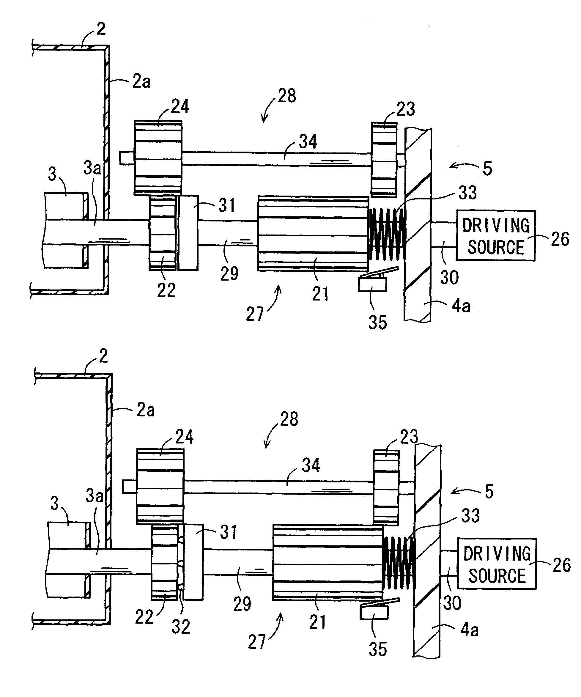
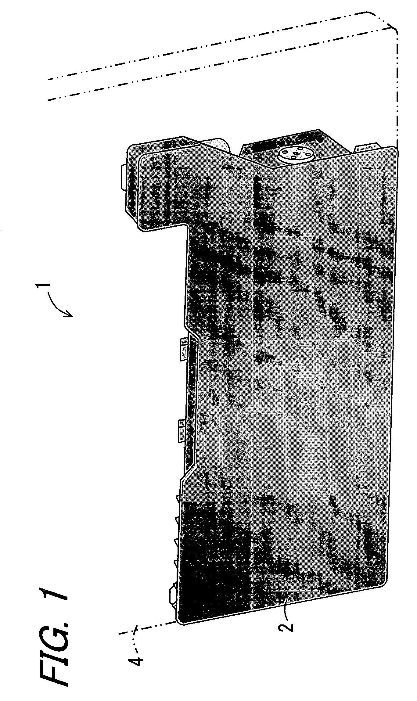
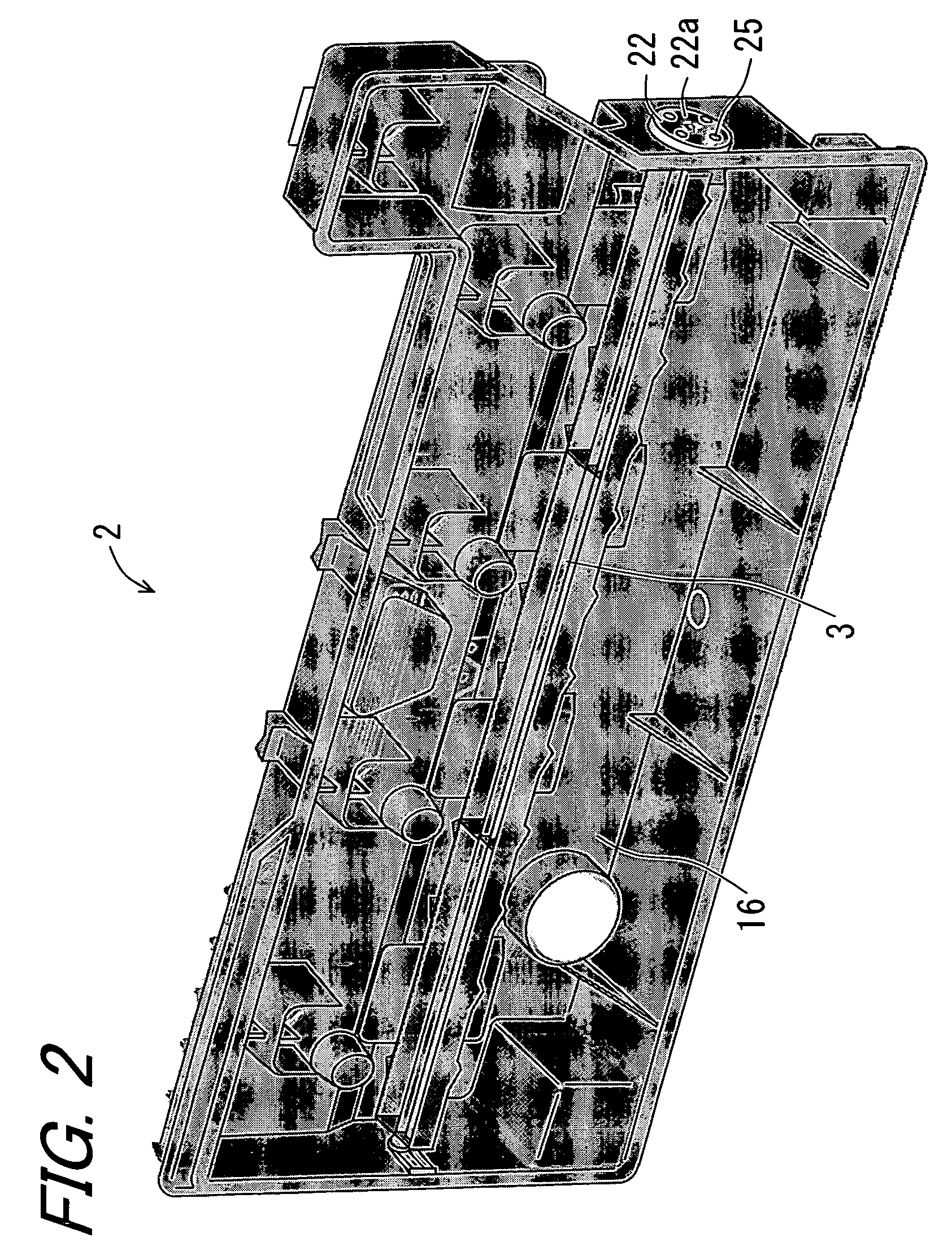
[0066]FIG. 1 is a perspective view showing an overview of a developer collecting apparatus 1 according to one embodiment of the invention. FIG. 2 is a view showing an internal constitution of a waste developer container 2 provided in the developer collecting apparatus 1. FIGS. 3A and 3B are views showing a configuration of a driving section 5 provided in the developer collecting apparatus 1. FIG. 4 is a view schematically showing an image forming apparatus 50 provided with the developer collecting apparatus 1, according to another embodiment of the invention.

[0067]With reference to FIG. 4, the developer collecting apparatus 1 is provided on the image forming apparatus 50 of which detail will be described hereinbelow. The image forming apparatus 50 comprises an image forming unit 51, an intermediate transfer body 52, a transfer portion 53, and cleaning sections 54 and 65. The image forming...


PUM


Abstract

A developer collecting apparatus for collecting waste developer which is generated by cleaning residual developer remained on a photoreceptor and an intermediate transfer body, includes: a waste developer container for accommodating the waste developer; a stirring member rotatably provided in the waste developer container, for stirring the waste developer; and a driving section for giving a rotary driving force to the stirring member. The driving section of the stirring member has: a driving source; a first driving force transmitting path and a second driving force transmitting path which are coupled on the driving source, for transmitting the rotary driving force to the stirring member, and when a rotational load on the first driving force transmitting path reaches a predetermined level or more, a switch-over of transmitting path can be performed from the first driving force transmitting path to the second driving force transmitting path.

Description

BACKGROUND OF THE INVENTION[0001]1. Field of the Invention[0002]The present invention relates to a developer collecting apparatus and an image forming apparatus having the developer collecting apparatus.[0003]2. Description of the Related Art[0004]In recent years, it has been gradually more common in an image forming apparatus to shift printing in black and white to printing in full color. Moreover, along with development of the image forming apparatus, a color image forming apparatus has been utilized for general purposes. Among the color image forming apparatuses, especially for an image forming apparatus which employs an electrophotographic system, an indirect transfer system has been often proposed in an attempt to meet miniaturization of the apparatus and speeding up of color image formation. The indirect transfer system is characterized by the following processes in formation of a color image onto recording paper. Firstly, a developer image is formed (first transfer) by stacki...

Claims


Application Information

Patent Timeline
Patent Type & Authority Patents(United States)
IPC IPC(8): G03G21/00
CPCG03G21/12G03G21/105G03G2215/1661G03G2221/1624G03G2221/0005
Inventor MURAKAMI, SUSUMUKADOWAKI, HIDEAKITAKAI, YASUHIRO
Owner SHARP KK
Why Eureka
Try Eureka