Accelerator pedal for motorized vehicle

a technology of accelerator pedals and motor vehicles, applied in the field of pedal mechanisms, can solve the problems of insufficiently emulating the tactile response of conventional accelerator pedals or too expensive prior art systems

Active Publication Date: 2008-07-29
CTS CORP ELKHART
View PDF30 Cites 47 Cited by
  • Summary
  • Abstract
  • Description
  • Claims
  • Application Information

AI Technical Summary

Benefits of technology

[0008]In a preferred embodiment, the pedal arm carries a magnet and a Hall effect position sensor is secured to the housing and responsive to the movement of the magnet for providing an electrical signal representative of pedal displacement.

Problems solved by technology

In this regard, prior art systems are either too costly or inadequately emulate the tactile response of conventional accelerator pedals.

Method used


Image

  • Accelerator pedal for motorized vehicle
  • Accelerator pedal for motorized vehicle
  • Accelerator pedal for motorized vehicle

Examples


Embodiment Construction

[0019]While this invention is susceptible to embodiment in many different forms, this specification and the accompanying drawings disclose only preferred forms as examples of the invention. The invention is not intended to be limited to the embodiments so described, however. The scope of the invention is identified in the appended claims.

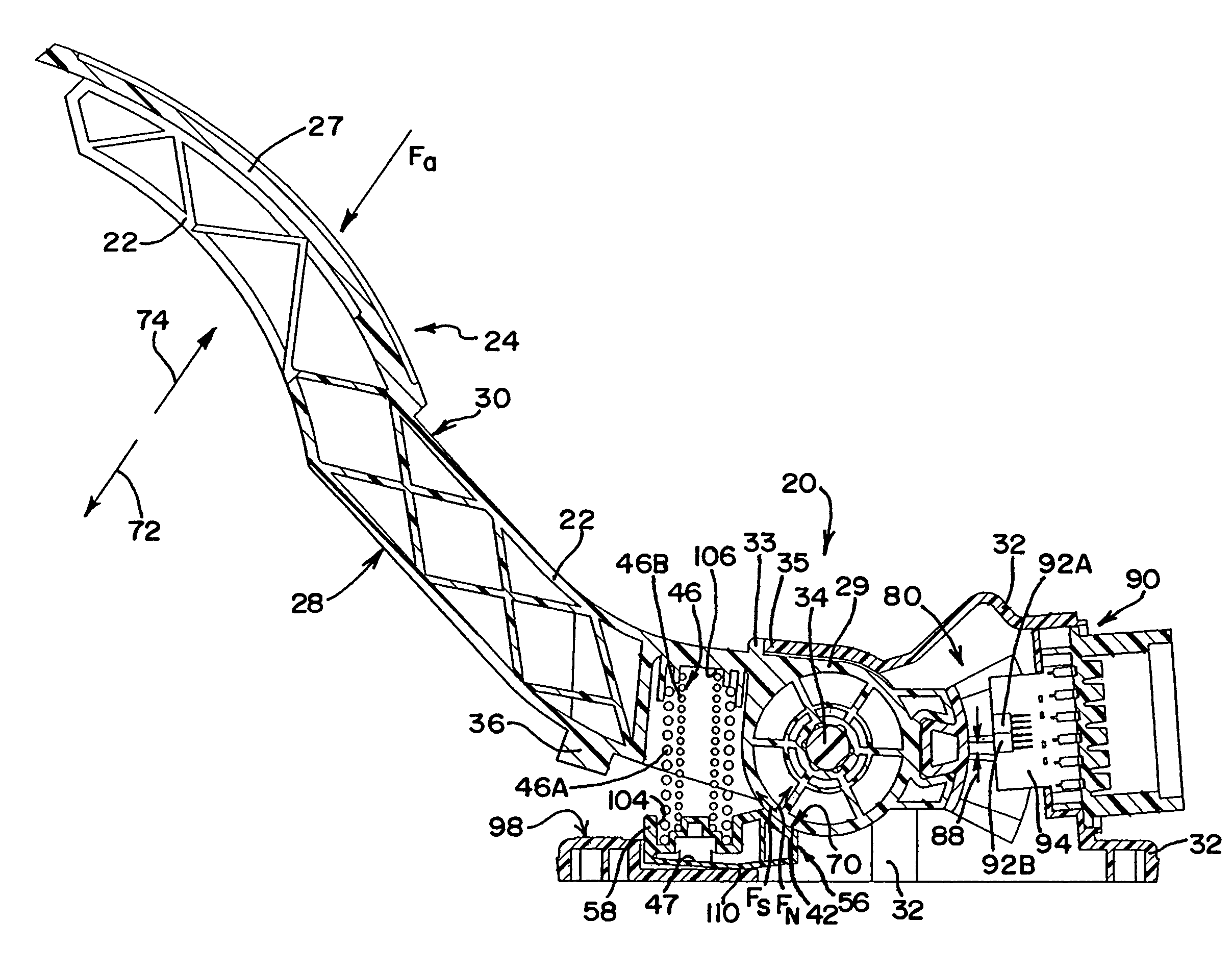
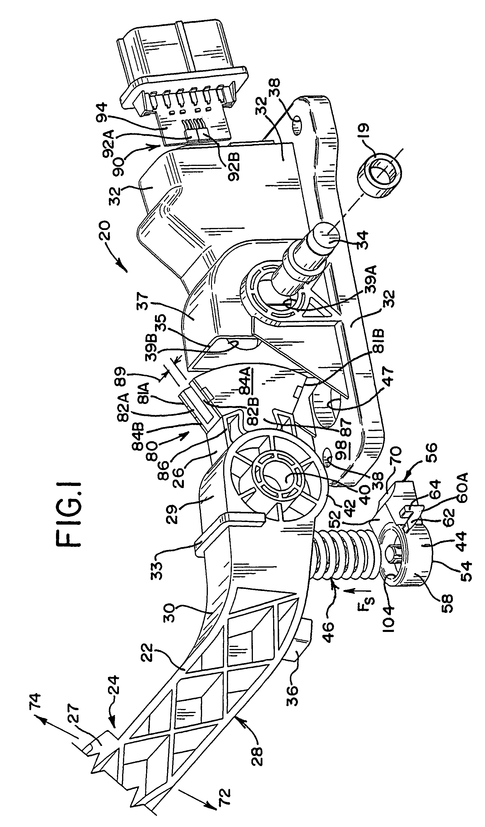
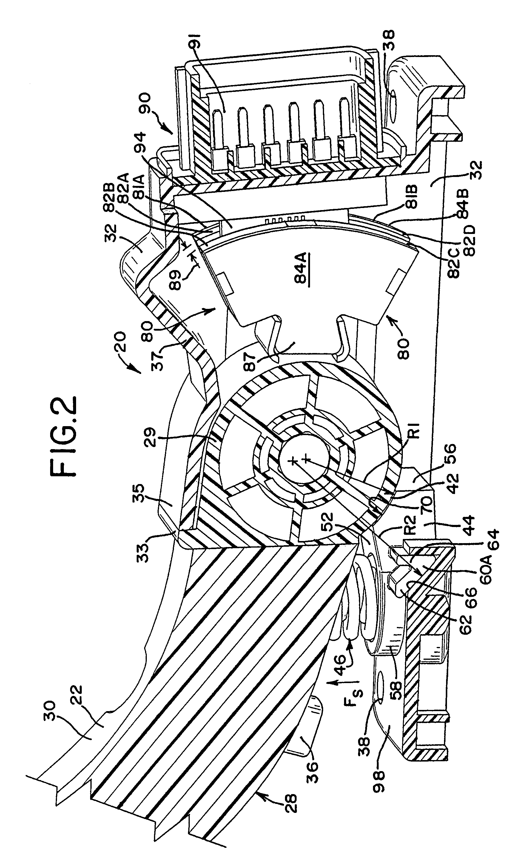
[0020]Referring to FIG. 1, a non-contacting accelerator pedal assembly 20 according to the present invention includes a housing 32, a pedal arm 22 rotatably mounted to housing 32, a brake pad 44 and a bias spring device 46. The labels “pedal beam” or “pedal lever” also apply to pedal arm 22. Likewise, brake pad 44 may be referred to as a “body” or “braking lever.” Pedal arm 22 has a footpad 27 at one end and terminates at its opposite proximal end 26 in a drum portion 29 that presents a curved, convex braking (or drag) surface 42. Pedal arm 22 has a forward side 28 nearer the front of the car and a rearward side 30 nearer the driver and rear of the ...


PUM


Abstract

An accelerator pedal assembly that provides a hysteresis in pedal force-response upon actuation is provided. The accelerator pedal assembly includes a housing, an elongated pedal arm terminating at one end in a rotatable drum defining a curved braking surface, a brake pad having a curved contact surface substantially complementary to the braking surface and a bias spring device operably situated between the pedal arm and the brake pad. The pedal arm is rotatably mounted to the housing such that the curved braking surface rotates as the pedal moves. The brake pad defines a primary pivot axis and is pivotably mounted for frictional engagement with the braking surface. The bias spring serves to urge the contact surface of the brake pad into frictional engagement with the braking surface of the drum.

Description

CROSS-REFERENCE TO RELATED APPLICATION[0001]This application claims the benefit of the filing date of U.S. Provisional Application Ser. No. 60 / 474,135, filed on 29 May 2003, which is explicitly incorporated by reference, as are all references cited therein.FIELD OF THE INVENTION[0002]This invention relates to a pedal mechanism. In particular, the pedal may be an accelerator pedal in a vehicle.BACKGROUND OF THE INVENTION[0003]Automobile accelerator pedals have conventionally been linked to engine fuel subsystems by a cable, generally referred to as a Bowden cable. While accelerator pedal designs vary, the typical return spring and cable friction together create a common and accepted tactile response for automobile drivers. For example, friction between the Bowden cable and its protective sheath otherwise reduce the foot pressure required from the driver to hold a given throttle position. Likewise, friction prevents road bumps felt by the driver from immediately affecting throttle pos...

Claims


Application Information

Patent Timeline
Patent Type & Authority Patents(United States)
IPC IPC(8): G05G1/30G05G1/38G05G5/03
CPCG05G1/38G05G5/03Y10T74/20534Y10T74/20528Y10T74/2054
Inventor WURN, MICHAEL L.
Owner CTS CORP ELKHART
Why Eureka
Try Eureka