Manifold assembly for reciprocating pump

a manifold and reciprocating technology, applied in the direction of pump components, positive displacement liquid engines, liquid fuel engine components, etc., can solve the problems of limited space for the fluid end, long continuous period of mud pumps,

Inactive Publication Date: 2008-07-29
S P M FLOW CONTROL
View PDF9 Cites 42 Cited by
  • Summary
  • Abstract
  • Description
  • Claims
  • Application Information

AI Technical Summary

Benefits of technology

[0009]The cylinder block assembly can have an inlet valve assembly that includes a first flange and a second flange connected by a column. In this inlet valve assembly the column extends through the discharge passage. The first flange in such an assembly defines a first cross-sectional area whi

Problems solved by technology

Typically, these mud pumps run for long continuous periods of time.
In

Method used


Image

  • Manifold assembly for reciprocating pump
  • Manifold assembly for reciprocating pump
  • Manifold assembly for reciprocating pump

Examples


Embodiment Construction

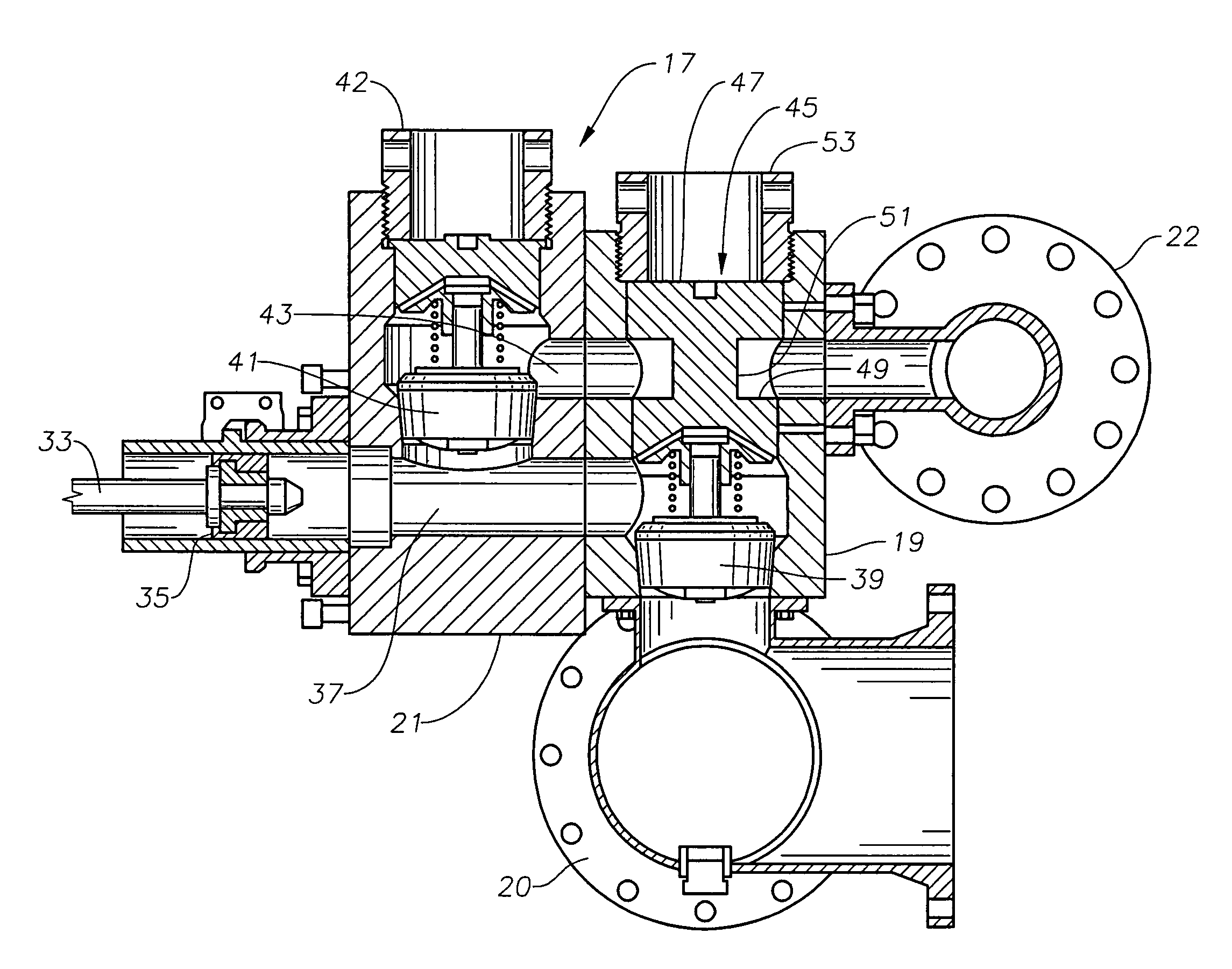
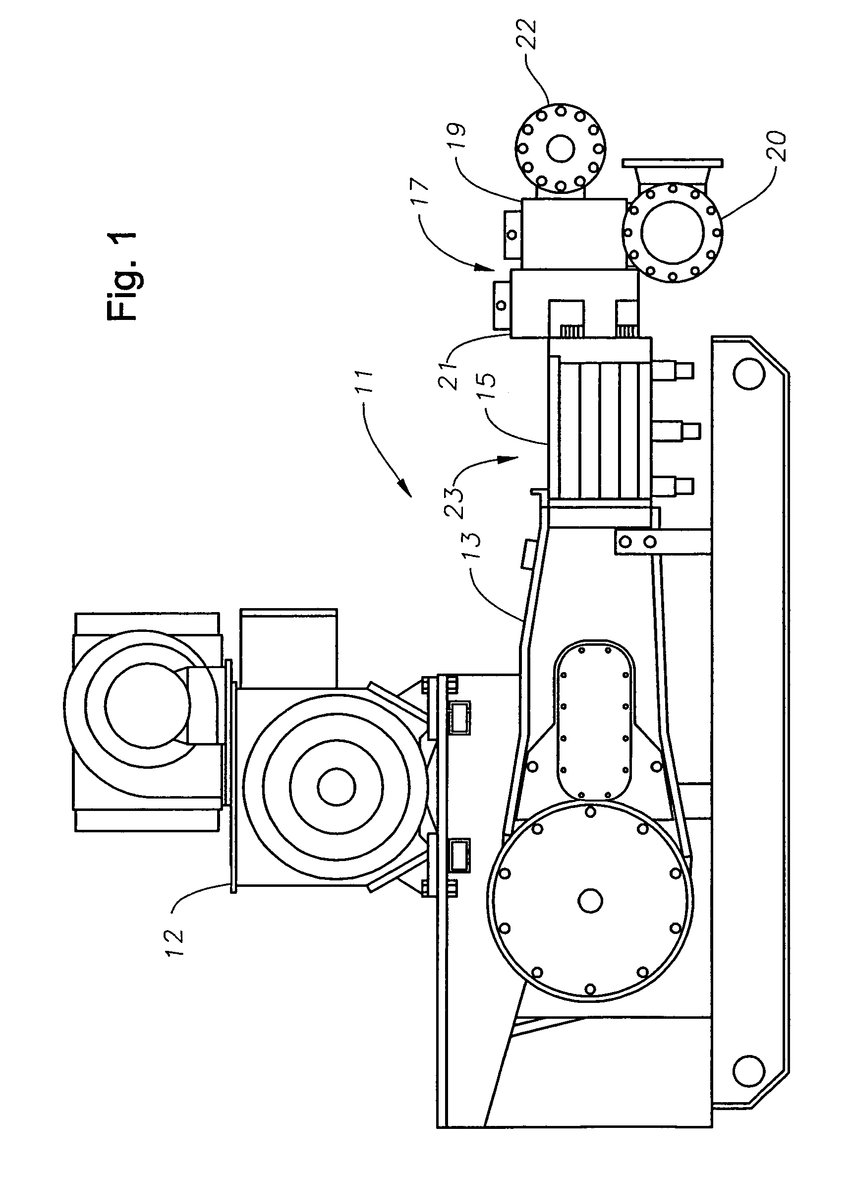
[0016]Referring to FIG. 1, a reciprocating pump 11 includes a crankshaft housing 13 that comprises a majority of the outer surface of reciprocating pump 11 shown in FIG. 1. A motor 12, located adjacent crankshaft housing 13, drives reciprocating pump 11. Motor 12 optionally transfers rotational movement to pump 11 through belts, chains, gears, or a direct coupling. A plunger or piston rod housing 15 attaches to a side of crankshaft housing 13 and extends to a cylinder or fluid end block 17. Fluid end block 17 preferably includes a plurality of cylinders, each with a fluid inlet portion 19 and a fluid outlet portion 21.

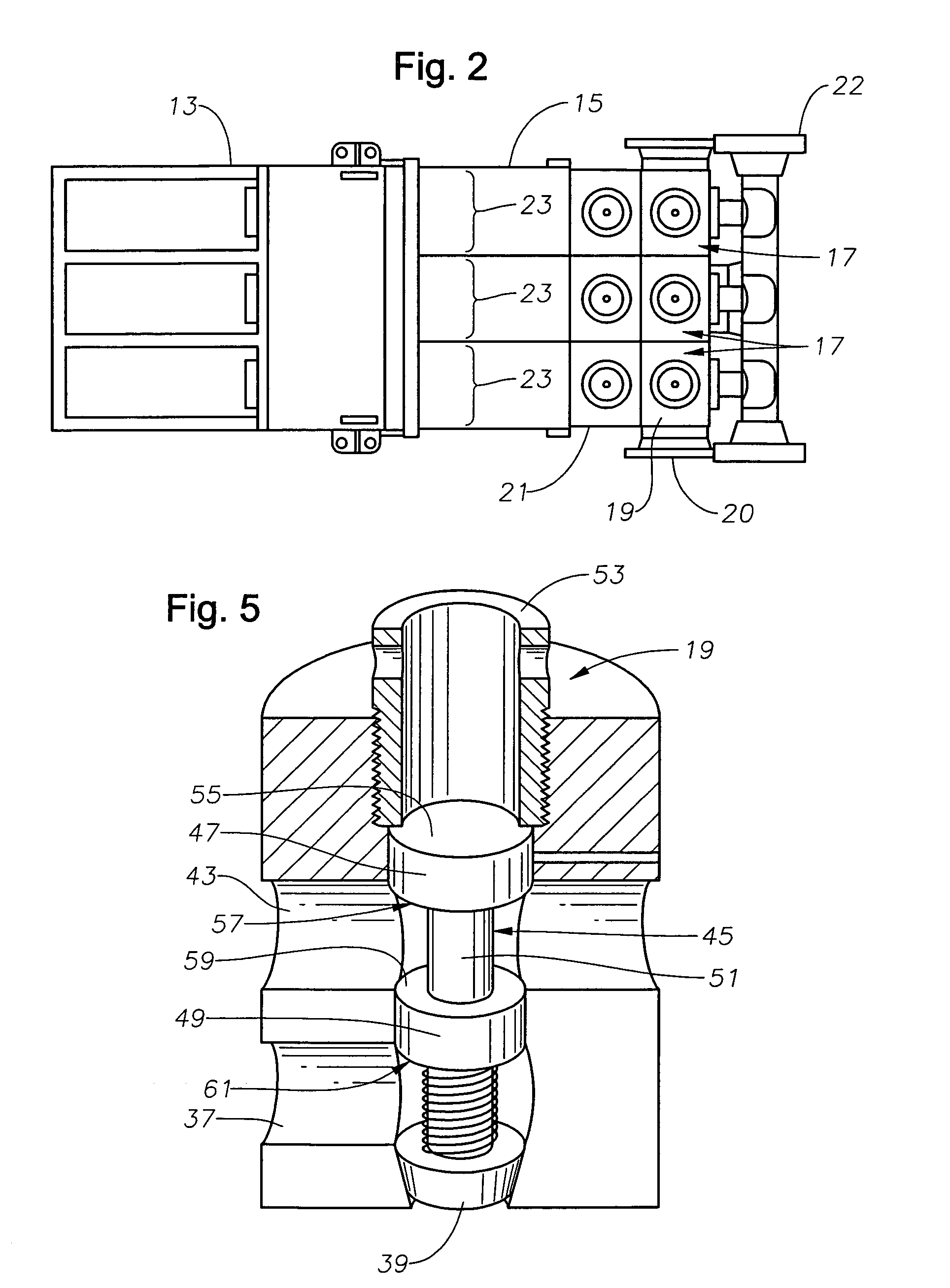
[0017]Referring to FIG. 2, piston rod housing 15 has several portions, each portion comprising a plunger or piston throw 23. Reciprocating pump 11 as shown in FIG. 2 has three piston throws 23, which is commonly know as a triplex, but could also be segmented for five piston throws 23, which is commonly known as a quintuplex pump. The description focuses on a triplex pu...


PUM


Abstract

A cylinder block assembly for a reciprocating pump includes a block body having a piston chamber that receives a piston of the reciprocating pump. The cylinder block assembly has an outlet valve assembly positioned within the block body that is positioned in fluid communication with the piston chamber. An outlet valve retainer retains the outlet valve relative to the piston chamber. The cylinder block assembly includes an inlet valve assembly extending through a side of the block body to the piston chamber. An inlet valve retainer also retains the inlet valve assembly relative to the piston chamber. A discharge passage extends from the outlet valve assembly to another side of the block body. A portion of the discharge passage extends between the inlet valve assembly and the inlet valve retainer.

Description

RELATED APPLICATIONS[0001]This nonprovisional patent application claims the benefit of provisional patent application U.S. Ser. No. 60 / 466,604, filed on Apr. 30, 2003, which is hereby incorporated by reference in its entirety.BACKGROUND OF THE INVENTION[0002]1. Field of the Invention[0003]The present invention relates generally to reciprocating pumps, and more specifically to a manifold assembly of an oil field mud or service pump.[0004]2. Background of the Invention[0005]In oil field operations, reciprocating pumps are often used for various purposes. Some reciprocating pumps are generally known as “service pumps” that are typically used for operations such cementing, acidizing, or fracing the well. Typically, these service pumps run for short periods of time, but on a frequent basis. Other reciprocating pumps, generally known as “mud pumps,” are typically used for circulating drilling mud downhole through a drill string and back up to the surface along the outer surface of the dri...

Claims


Application Information

Patent Timeline
IPC IPC(8): F04B39/00F04B11/00F04B39/10F04B53/10F04B39/12
CPCF04B53/1032F04B39/122
Inventor KUGELEV, VLADIMIRMATZNER, MARK D.
Owner S P M FLOW CONTROL
Why Eureka
Try Eureka