Random number generating device

a technology of random number generation and generating device, which is applied in the field of random number generation device, can solve the problems of increasing security level, circuit size inevitably becoming large, and circuit size there of being large, and achieve the effect of small circuit size and small output bias valu

Inactive Publication Date: 2008-07-29
KK TOSHIBA
View PDF9 Cites 19 Cited by
  • Summary
  • Abstract
  • Description
  • Claims
  • Application Information

AI Technical Summary

Benefits of technology

[0013]The present invention is proposed in consideration of the above problems, and the object of the present invention is to provide a random number generating device having a smaller circuit size, and a smaller value of output bias.

Problems solved by technology

However, since the random number generated in such a manner are pseudo-random numbers, if there are considerably many numbers, a periodicity appears, thereby decreasing the security level.
Accordingly, in order to generate high-quality random numbers, the circuit size inevitably becomes large.
Thus, conventional random number generating devices have problems in that the circuit size there of is large, and the outputs thereof are biased.

Method used


Image

  • Random number generating device
  • Random number generating device
  • Random number generating device

Examples


first embodiment

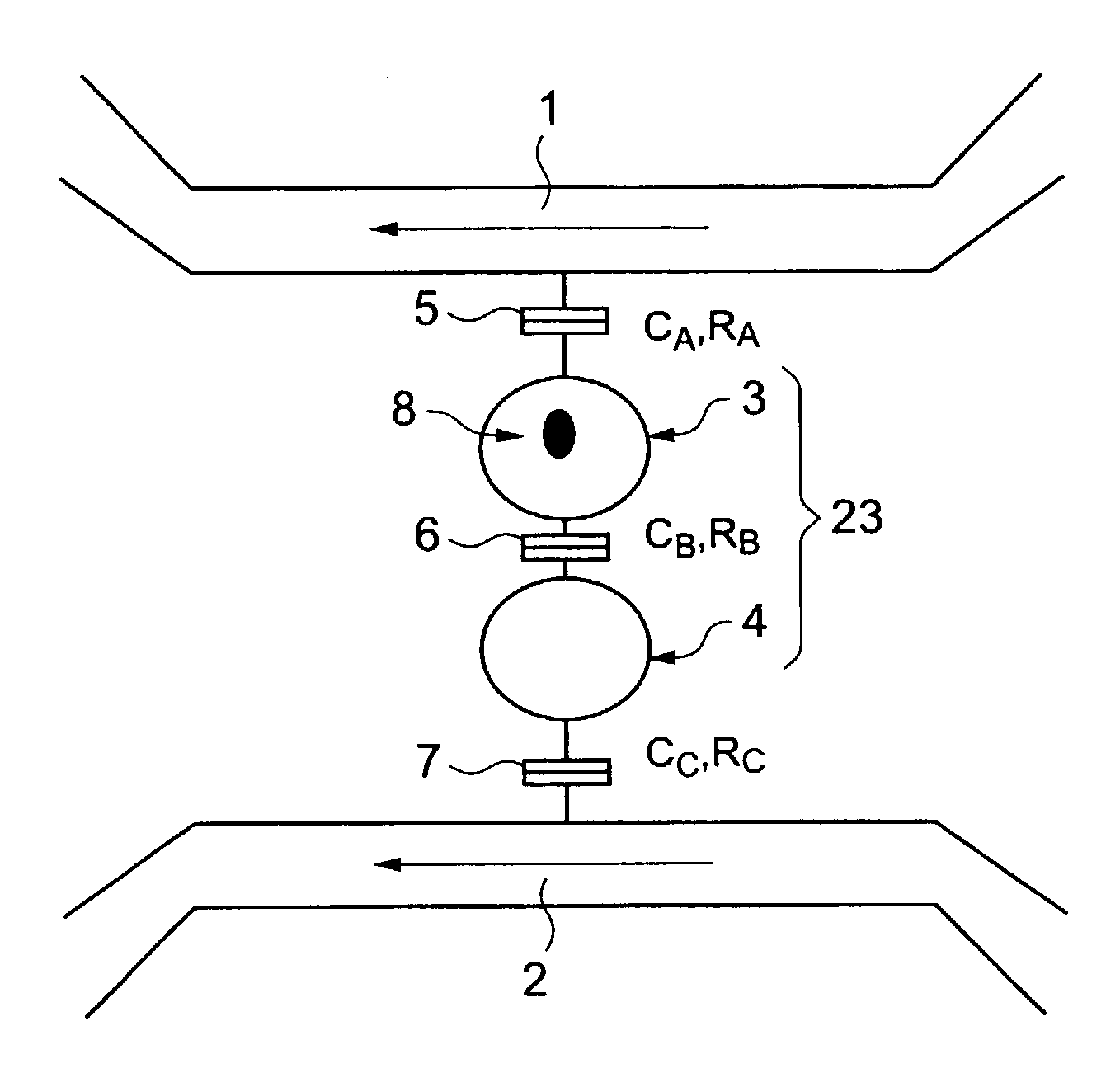
[0042]FIG. 1 is a conceptual view of a random number generating device according to the first embodiment of the present invention.

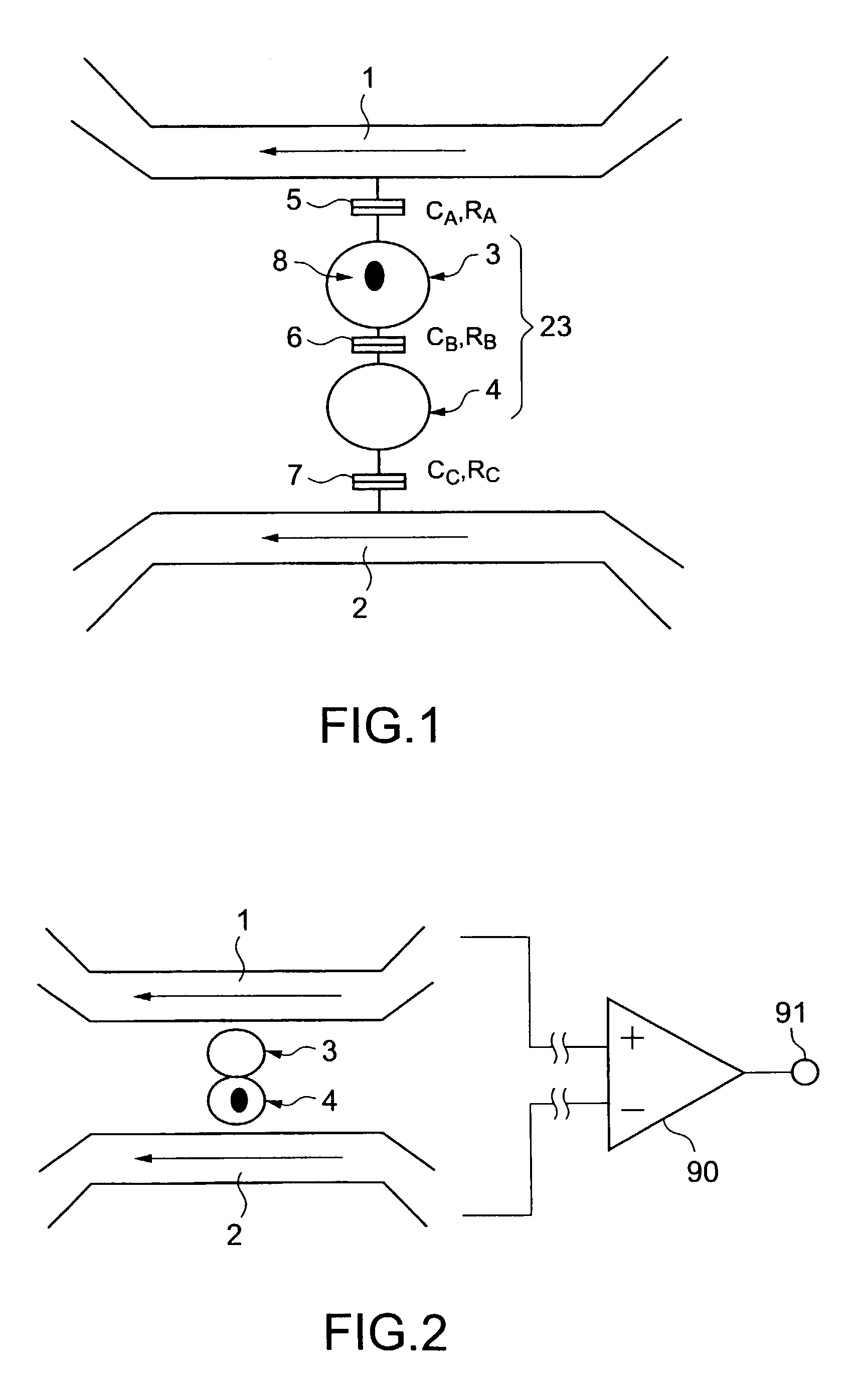
[0043]As shown in FIG. 1, the random number generating device includes a pair of first current path 1 and second current path 2, which are placed in parallel with each other, and a pair of first nanoparticle 3 and second nanoparticle 4, which are capable of exchanging electric charges, and are located between the first current path 1 and the second current path 2.

[0044]The size of the first nanoparticle 3 and the second nanoparticle 4 is sufficiently small to enjoy the effects of the wave function of charges. For example, the diameter of the nanoparticles is 100 nm or less. Such nanoparticles are called “quantum dots.” In a quantum dot, the energy level including charging energy of a charge is discrete.

[0045]Further, the first nanoparticle 3 and the second nanoparticle 4 are electrically coupled via a tunnel barrier 6 having a capacitance of CB and a resi...

second embodiment

[0076]Next, a random number generating device according to the second embodiment of the present invention will be described with reference to FIGS. 5A to 5C.

[0077]In this embodiment, the effect of the interaction between the temporal changes in potential distribution of a capacitance network, the charge state of which is not stable, and the temporal fluctuations in current is mainly used.

[0078]As shown in FIG. 5A, the random number generating device includes a pair of first current path 1 and second current path 2 arranged in parallel with each other, a microparticle 9 which has a diameter of 1 μm or less and is located between the first current path 1 and the second current path 2, a first insulating layer 10 located between the microparticle 9 and the first current path 1, and a second insulating layer 11 located between the microparticle 9 and the second current path 2.

[0079]With such a structure, at least one of a first capacitance constituted by the first current path 1, the fi...

third embodiment

[0089]Next, a random number generating device according to the third embodiment of the present invention will be described.

[0090]In this embodiment, the effect of the strong interaction between the current paths and the charges in the material placed between the current paths to fluctuate the current values is used in the case where there is not a big difference between the plasma frequency inherent to the material placed between the current paths and the degree of temporal fluctuations of currents.

[0091]FIG. 6A shows the structure of a random number generating device according to this embodiment.

[0092]In this embodiment, there is a structure 13 between the first current path 1 and the second current path 2. The structure 13 is either charged or polarized, and the cycle of the plasma oscillation is about the same as time ΔtI (the above-described formula) in which an electron in the currents flowing through the first current path 1 and the second current path 2 pass by a region corre...


PUM


Abstract

The objective is to provide a random number generating device having a smaller circuit size and a smaller value of output bias. The random number generating device includes a pair of first and second current paths arranged in parallel with each other, and a pair of first and second fine particles, which can mutually exchange charges, and are located in the vicinity of the first and second current paths.

Description

CROSS-REFERENCE TO RELATED APPLICATIONS[0001]This application is based upon and claims the benefit of priority from the prior Japanese Patent Application No. 2002-54153, filed on Feb. 28, 2002, the entire contents of which are incorporated by reference herein.BACKGROUND OF THE INVENTION[0002]1. Field of the Invention[0003]The present invention relates to a random number generating device.[0004]2. Related Background Art[0005]As a result of the improvement in information communication networks, such as Internet, commercial transactions such as bank payments are carried out through information communication networks. As such opportunities increase, a demand for higher security arises, resulting in that various kinds of cryptosystems are developed.[0006]In such cryptosystems, it is necessary to generate high-quality random numbers in order to improve the security level. The term “high-quality” means that there is no periodicity in random numbers, that it is impossible to predict the ran...

Claims


Application Information

Patent Timeline
Patent Type & Authority Patents(United States)
IPC IPC(8): H01L23/58G06F7/58G09C1/00H01L29/06H01L29/66H01L29/788H03K3/84
CPCB82Y10/00H04L9/0861H01L29/7888G06F7/588
Inventor TANAMOTO, TETSUFUMIFUJITA, SHINOBU
Owner KK TOSHIBA
Why Eureka
Try Eureka