
Ultrasound emitting system for high frequency ultrasonic diagnostic equipment

A technology of ultrasonic diagnosis and emission system, which is applied in the direction of acoustic wave diagnosis, infrasonic wave diagnosis, ultrasonic/sonic wave/infrasonic wave diagnosis, etc. It can solve the problems of large number of transmitting circuit components, short circuit, manufacturing cost, high volume and high power consumption, and improve the emission Energy, reduced circuit size, and hardware cost-effective effects

Inactive Publication Date: 2011-02-16
INST OF BIOMEDICAL ENG CHINESE ACAD OF MEDICAL SCI
View PDF4 Cites 15 Cited by
  • Summary
  • Abstract
  • Description
  • Claims
  • Application Information

AI Technical Summary

Problems solved by technology

Therefore, the number of transmitting circuit components formed in the traditional way is large, resulting in high manufacturing cost, volume and power consumption, which is not conducive to the development of portable ultrasonic diagnostic equipment; at the same time, because the two outputs of the FET driver are not completely synchronized, it may The two field effect transistors are turned on at the same time, so that the high voltage power supply connected to the field effect transistor driver and the ground are short-circuited, which will cause the risk of circuit damage and poor reliability
Especially when the detection frequency reaches the high-frequency range of 10-20MHz, the narrow trigger pulse will reduce the emission energy, the echo information will be easily overwhelmed by noise, the signal-to-noise ratio will decrease, and the detection depth will decrease

Method used


Image

  • Ultrasound emitting system for high frequency ultrasonic diagnostic equipment
  • Ultrasound emitting system for high frequency ultrasonic diagnostic equipment
  • Ultrasound emitting system for high frequency ultrasonic diagnostic equipment

Examples


Embodiment Construction

[0039] In order to make the object, technical solution and advantages of the present invention clearer, the implementation manner of the present invention will be further described in detail below in conjunction with the accompanying drawings.

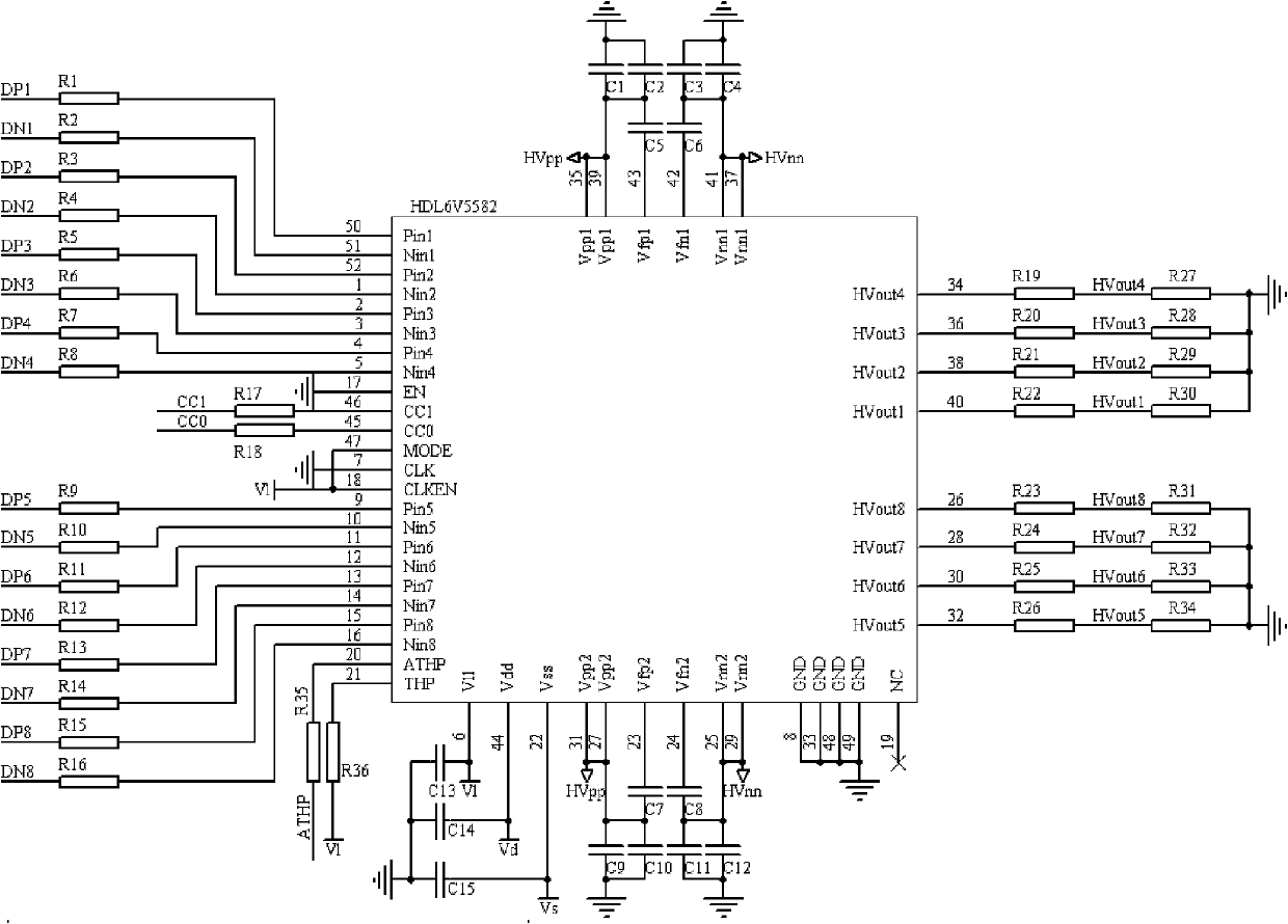
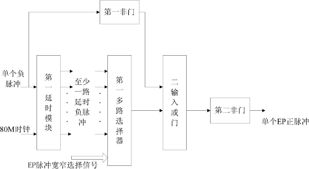
[0040] In order to overcome the deficiencies of the prior art, reduce manufacturing costs, reduce the size and power consumption of transmitting circuit components; when the detection frequency reaches the high-frequency range of 10-20MHz, improve the transmission energy, signal-to-noise ratio and detection depth, the embodiment of the present invention provides An ultrasonic transmission system used in high-frequency ultrasonic diagnostic equipment, see figure 1 , see the description below:

[0041] The ultrasonic emission system includes: high-frequency array ultrasonic transducer, high-voltage matrix switch circuit, emission drive circuit and FPGA control circuit,

[0042] The high-voltage matrix switch circuit connects the array e...


PUM


Abstract

The invention discloses an ultrasound emitting system for high frequency ultrasonic diagnostic equipment, and belongs to the technical field of medical ultrasonic diagnosis technology. The ultrasound emitting system comprises a high frequency array ultrasonic transducer, a high voltage matrix switching circuit, an emitting driving circuit and a field programmable gate array (FPGA) control circuit, wherein the high voltage matrix switching circuit connects array elements of the high frequency array ultrasonic transducer with various emitting channels of the emitting driving circuit, and performs circular switching according to the scanning sequence of ultrasonic beams during ultrasonic imaging; the emitting driving circuit generates high voltage pulses to act on the high frequency array ultrasonic transducer to generate ultrasound; and the FPGA control circuit controls the switching between the high frequency array ultrasonic transducer and the various emitting channels of the emitting driving circuit to generate trigger pulses of the emitting driving circuit. The circuit volume of the whole ultrasound emitting system is reduced, the number of used components is greatly decreased and the hardware cost is effectively controlled.

Description

technical field [0001] The invention relates to the technical field of medical ultrasonic diagnosis, in particular to an ultrasonic emission system used in all-digital portable high-frequency ultrasonic diagnostic equipment. Background technique [0002] In medical ultrasound imaging equipment, the quality of the ultrasound waveform entering the human tissue directly affects the quality of the echo information downstream of the signal chain and the clarity of the final image. In clinical application, the ultrasonic transmission system needs to timely adjust the ultrasonic frequency, peak-to-peak value, duty cycle and pulse number and other parameters according to the depth change of the measured tissue, the switching of scanning mode and the needs of color Doppler blood flow imaging. Make adjustments. [0003] In the ultrasonic imaging system in the prior art, each transmitting channel needs to independently drive two FETs in a FET pair, and the number of FET pairs is the s...

Claims


Application Information

Patent Timeline
Patent Type & Authority Applications(China)
IPC IPC(8): A61B8/00A61B8/06
Inventor 王延群王晓春计建军周盛杨军宋学东李穗
Owner INST OF BIOMEDICAL ENG CHINESE ACAD OF MEDICAL SCI
Learn More