
Image navigation device

a navigation device and image technology, applied in the direction of navigation instruments, instruments, television systems, etc., can solve the problems of inability to know the correct position at a position, the apparatus becomes large and heavy, and the difficulty of installing the position and angle sensor

Inactive Publication Date: 2008-07-29
MITSUBISHI ELECTRIC CORP
View PDF6 Cites 15 Cited by
  • Summary
  • Abstract
  • Description
  • Claims
  • Application Information

AI Technical Summary

Benefits of technology

[0027]According to a video navigation apparatus relating to the next invention, the video navigation apparatus further comprises a control unit that controls the photographing unit to maintain a predetermined angle that is determined bas

Problems solved by technology

Therefore, there has been a problem that the apparatus becomes large and heavy.
However, there has been a problem that it is difficult to install the position and angle sensor 1 and also obtain a compact and light apparatus suitable for carrying.
When a GPS is utilized as a position sensor, for example, there has been a problem that it is not possible to know a correct position at a position like in a tunnel or a shade of a building where a wave of a GPS satellite does not reach.
Therefore, there has been a problem that the user is misled to a wrong direction.
However, according to the method of correcting a measured result disclosed in the publication 3, the following problems occur.
However, at a position where it is not possible to set an object having substantially a fixed shape like a signal mechanism or a road sign as a mark, it is not possible to estimate a camera position.
However, when a search range becomes large, the processing quantity of pattern matching processing increases, and precision tends to become lower.
Consequently, according to the method of correcting an error of a measured result, there has been a problem that it is hard to process the pattern matching in a short time and in high precision.
Therefore, when a procedure is to make a left turn at the first time and make a right turn at the second time at the same point A, for example, both an arrow mark of the left turn and an arrow mark of the right turn are displayed at the point A. Consequently, there is a problem that it is not possible to give proper guidance.

Method used


Image

  • Image navigation device
  • Image navigation device
  • Image navigation device

Examples


first embodiment

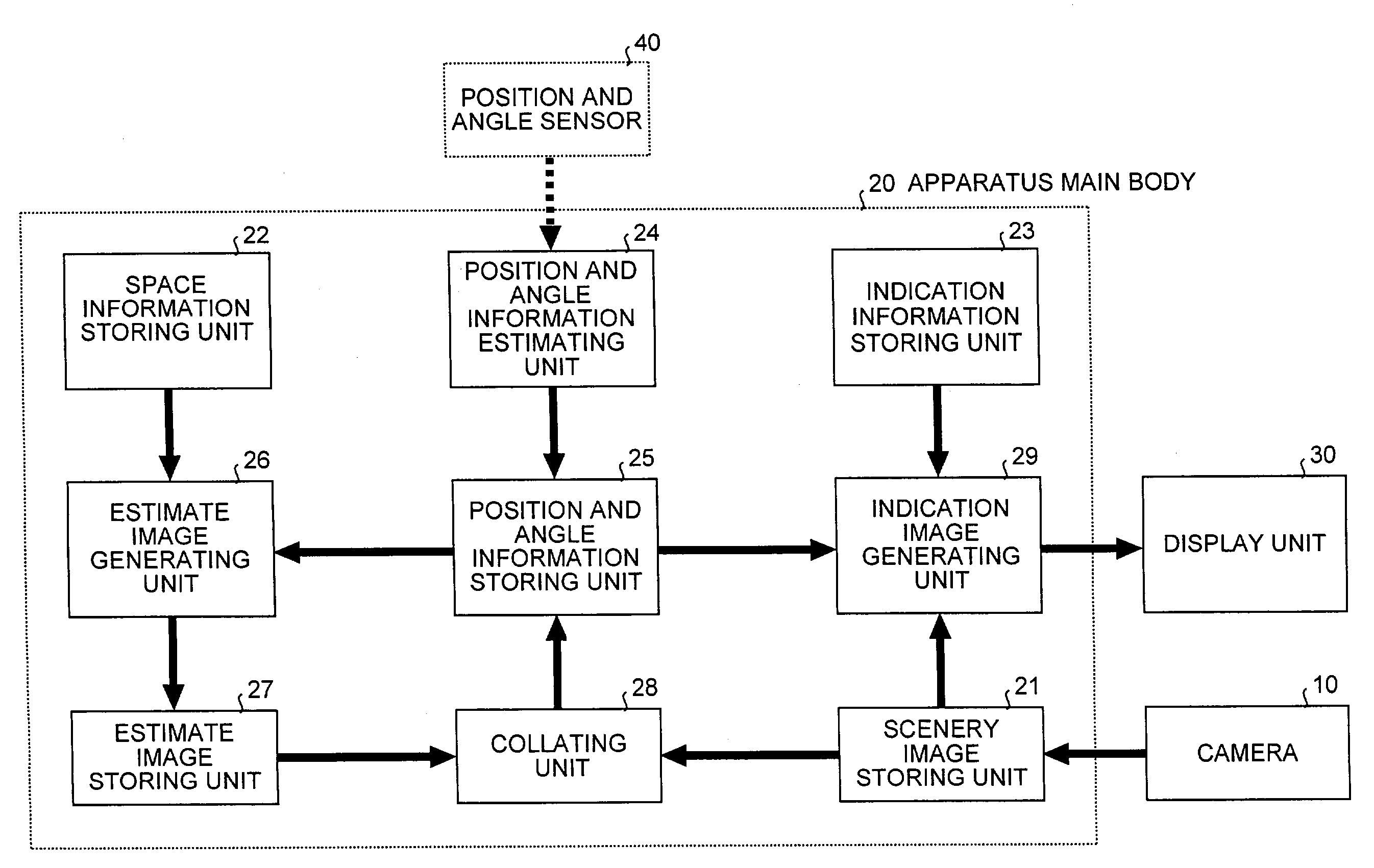
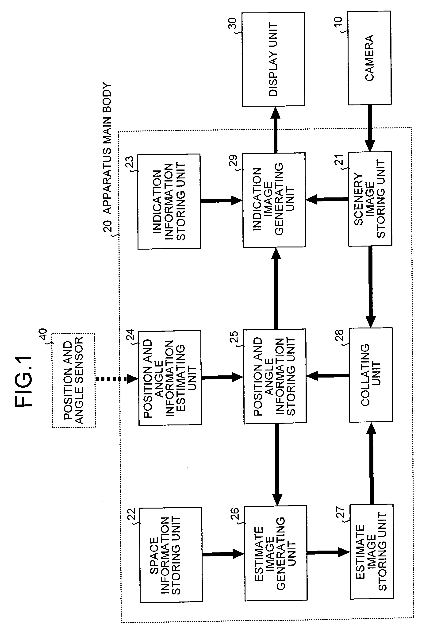
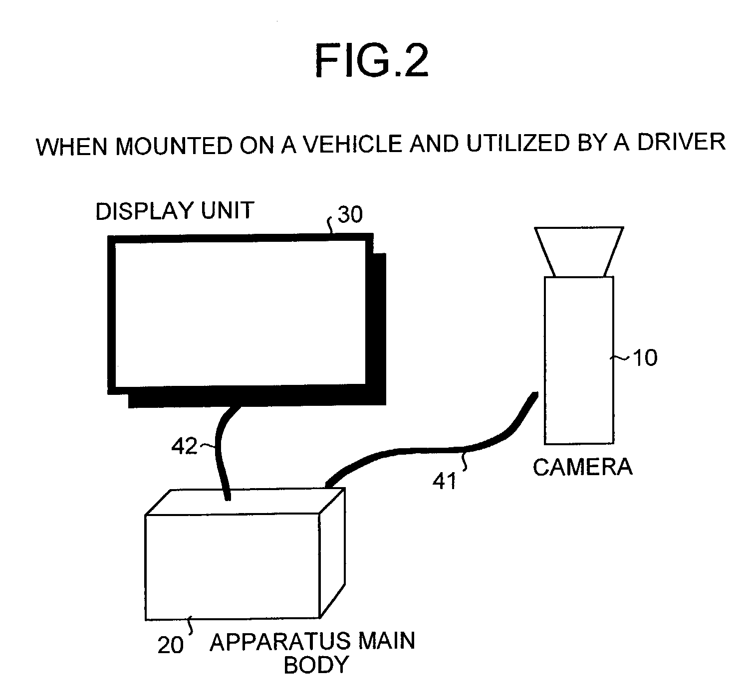
[0065]FIG. 1 shows a structure diagram of a video navigation apparatus according to the present invention, and FIG. 2 shows an appearance view of the video navigation apparatus in a mode that the video navigation apparatus of the present invention is built into a vehicle.

[0066]As shown in FIG. 2, the video navigation apparatus is constructed of a camera 10, which is a visible camera, an apparatus main body 20, and a display unit 30, for example.

[0067]The camera 10 is installed at a position where it is possible to obtain a scene close to a field of vision of a driver, such as on the roof of the vehicle or near the windshield within the vehicle, and is connected to the apparatus main body 20 with a cable 41. A video signal output by the camera 10 is transmitted to the apparatus main body 20 via the cable 41 according to a format called the NTSC, for example.

[0068]The apparatus main body 20 is a computer that includes a CPU (central processing unit) and a storing unit, and executes a ...

second embodiment

[0117]A second embodiment of this invention will be explained. A video navigation apparatus relating to this embodiment has such a structure that, in the structure of the video navigation apparatus shown in FIG. 1, both an angle sensor and a position sensor are employed as the position and angle sensor 40, and these sensors are connected to an input and output data interface not shown via a cable not shown. The position sensor may not have higher precision than that of the first embodiment.

[0118]The angle sensor and the position sensor are employed as the position and angle sensor 40 for the following reason. Even when only a position sensor having relatively high precision is connected to a apparatus main body, it may not be possible to obtain sufficient precision depending on a kind of the position sensor. Therefore, when the precision of the position sensor is not so satisfactory, a position and angles of the camera 10 are estimated based on sensor information from both the angle...

third embodiment

[0125]A third embodiment of this invention will be explained. FIG. 12 shows a structure diagram of a video navigation apparatus relating to the third embodiment. The video navigation apparatus relating to this third embodiment has such a structure that, in the structure of the video navigation apparatus shown in FIG. 1, the space information storing unit 22 is deleted, and an actual photograph image storing unit 300 is added. In FIG. 12, portions that achieve functions similar to those of the constituent elements shown in FIG. 1 are attached with the same symbols.

[0126]The actual photograph image storing unit 300 stores in advance position information and angle information of a camera 10 and an actual photograph image photographed at this position as a set. The actual photograph image storing unit 300 stores actual photograph images photographed at a plurality of points in advance.

[0127]The position information, the angle information, and the actual photograph image are stored as a ...


PUM


Abstract

An estimate image is generated from a position and an angle of a camera and the estimate image is stored. A collating unit collates an estimate image with a scenery image, and corrects estimate values of a position and angles of the camera according to a result of the collation. An indication image generating unit generates an indication image by processing indication information stored in an indication information storing unit, based on position information that shows a position of the camera and angle information that shows angles of the camera after the correction processing stored in a position and angle information storing unit.

Description

[0001]This application is the national phase under 35 U.S.C. § 371 of PCT International Application No. PCT / JP02 / 04079 which has an International filing date of Apr. 24, 2002, which designated the United States of America.TECHNICAL FIELD[0002]The present invention relates to a video navigation apparatus that provides a driver or a pedestrian with indication information such as a route guidance with an image using an information terminal mounted on a vehicle or a portable information terminal.BACKGROUND ART[0003]As examples of a conventional video navigation apparatus, there have been known a navigation apparatus disclosed in Japanese Patent Application Laid-open No. 9-33271 (publication 1), and a car navigation system disclosed in Japanese Patent Application Laid-open No. 11-108684 (publication 2). A principle that is common to the video navigation apparatuses in the publications 1 and 2 is shown in FIG. 23.[0004]In FIG. 23, a position and angle sensor 1 detects a position and angle...

Claims


Application Information

Patent Timeline
IPC IPC(8): H04N7/18G01C21/00G01C21/36G08G1/0969
CPCG01C21/3602
Inventor WAKIMOTO, KOJITANAKA, SHOJIMASUOKA, HIROAKI
Owner MITSUBISHI ELECTRIC CORP
Learn More