Wheel assembly

a technology of wheels and components, applied in the field of wheels, can solve the problems of failure to rotate and thus be useless, and achieve the effects of preventing deformation, prolonging life, and effectively trigging up

Inactive Publication Date: 2008-08-05
HAION CASTER IND
View PDF13 Cites 26 Cited by
  • Summary
  • Abstract
  • Description
  • Claims
  • Application Information

AI Technical Summary

Benefits of technology

[0006]To obviate the above drawback, accordingly, an object of the present invention is to provide a wheel assembly which prevents from deformation and is trigged up effectively and which has prolonged lives.

Problems solved by technology

Consequently, the wheels are easy to scrape or deform, resulting in failure to rotate and thus being useless.

Method used


Image

  • Wheel assembly
  • Wheel assembly
  • Wheel assembly

Examples


Embodiment Construction

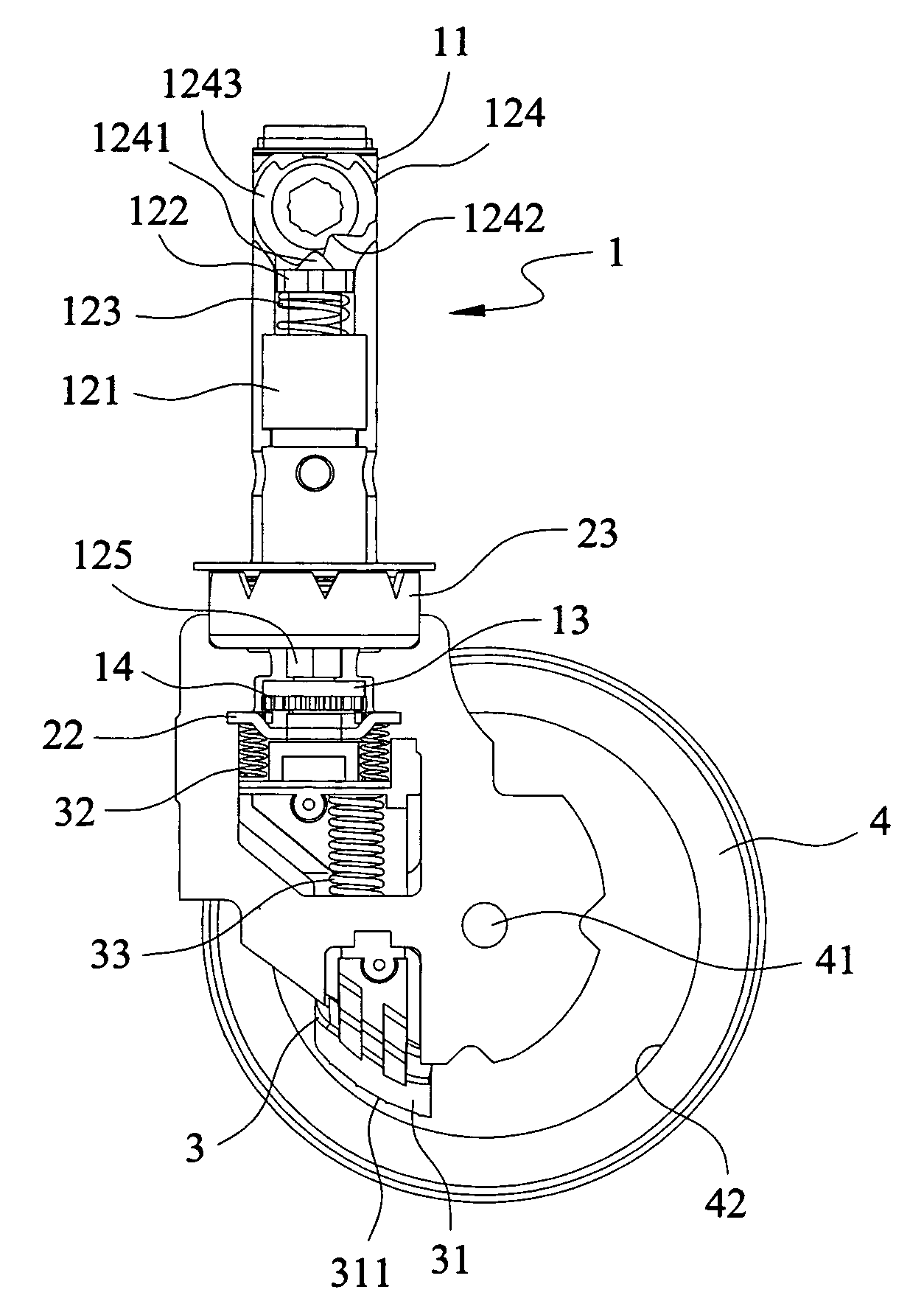
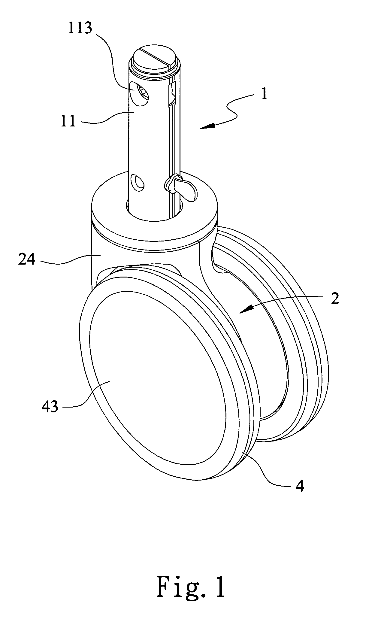
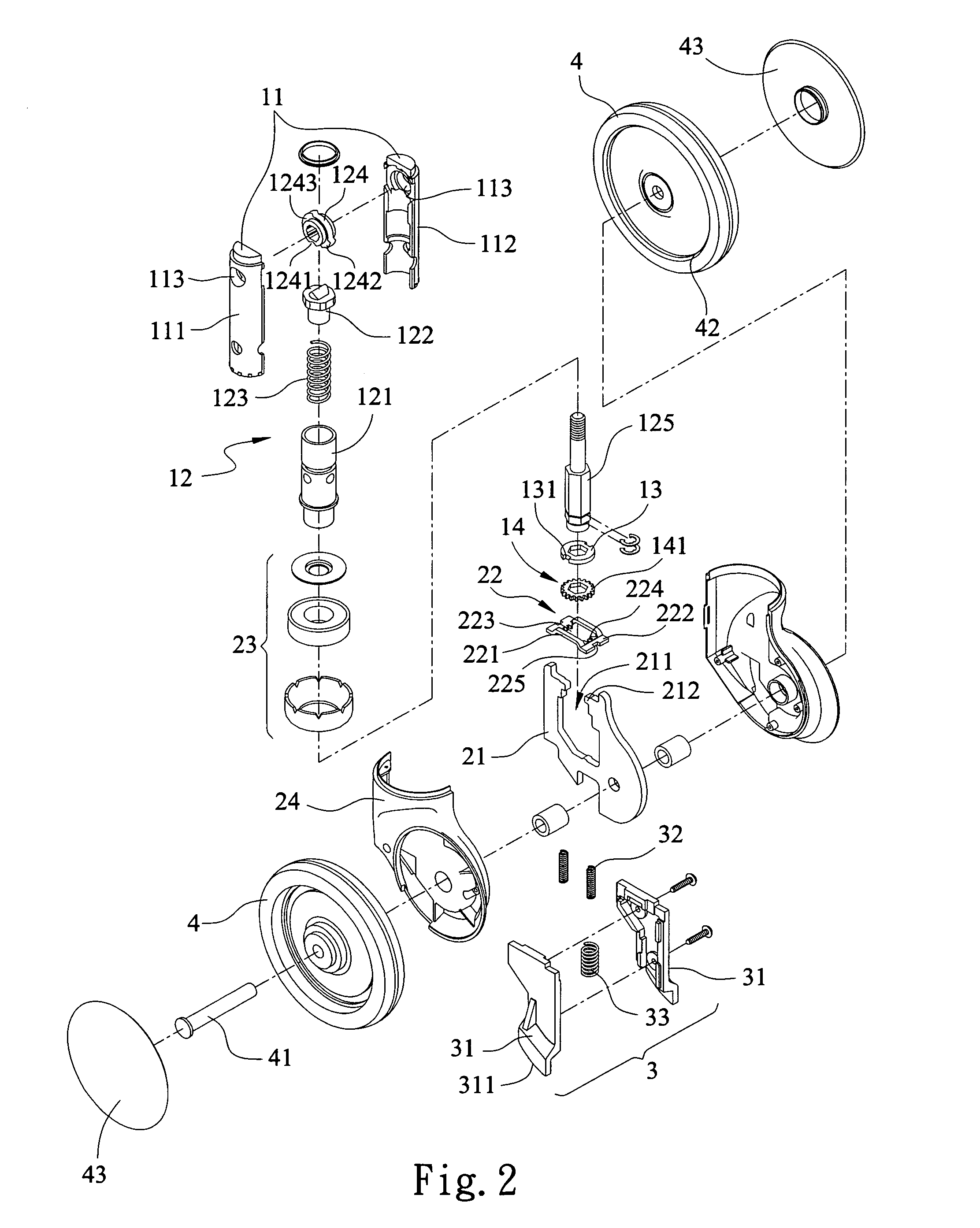
[0013]With reference to FIGS. 1, 2 and 3, a wheel assembly in accordance with the present invention comprises a swiveling shaft 1, a support member 2, an arresting member 3 and wheels 4. The swiveling shaft 1 at least comprises a swiveling sleeve 11, a pressing element 12 disposed on the swiveling sleeve 11, and a first gear bracket 13 and a second gear bracket 14 located on an end of the pressing element 12. The swiveling sleeve 11 has a first casing 111 and a second casing 112. Through holes 113 are respectively defined in the first casing 111 and the second casing 112 and correspond to each other for allowing a rotating level (not shown) to extend therethrough and actuate the pressing element 12. The pressing element 12 comprises an axle sleeve 121, a pushing portion 122 partly extending into the axle sleeve 121, a resilient portion 123, a rotating portion 124 and an axle pole 125. The rotating portion 124 abuts an end of the pushing portion 122 and corresponds to the through hol...


PUM


Abstract

A wheel assembly has a swiveling shaft, a support member movably assembled with the swiveling shaft, an arresting member and wheels. The swiveling shaft includes a swiveling sleeve, a pressing element disposed on the swiveling sleeve, and a first gear bracket and a second gear bracket. The support member includes a rack with an opening, and a third gear bracket snapped in the opening, The arresting member is mounted on the rack. A first resilient element is provided between the arresting member and the rack. A second resilient element is provided between the arresting member and the third gear bracket. The wheels respectively pivot to the rack, and are limited at opposite sides of the arresting member. The pressing element limits rotation of the wheels, preventing deformation of the wheels thereby effectively stopping the wheels and lengthening lives of the wheels.

Description

BACKGROUND OF THE INVENTION[0001](a) Field of the Invention[0002]The present invention relates to a wheel assembly, and particularly to a wheel assembly which prevents from deformation and stops effectively.[0003](b) Description of the Prior Art[0004]A conventional truckle wheel assembly substantially comprises a base and wheels pivoting to the base. An arresting member is disposed between the base and the wheels. The arresting member is a metal plate attached to the wheel. A shaft is provided on an end of the base for assembling the wheels to a bottom of an object. The wheels rotate to move the object, and at the same time, cooperate with the shaft to bring the base to rotate the wheels in multi-directions. As the object arrives at a predetermined position, the arresting member presses the wheels to stop.[0005]However, the truckle wheel assembly is normally made of material like plastic, rubber etc. The wheels are pressed by the arresting member repeatedly, and evenly, are pushed / p...

Claims


Application Information

Patent Timeline
Patent Type & Authority Patents(United States)
IPC IPC(8): B60B33/00
CPCB60B33/0021B60B33/0042B60B33/0049B60B33/0057B60B33/0068B60B33/0073B60B33/0092B60B33/021B60B33/025B60B33/026B60B33/0086Y10T16/195Y10T16/184
Inventor CHOU, CHUAN-HAI
Owner HAION CASTER IND
Why Eureka
Try Eureka