Device for determining a steering angle and a torque that is exerted on a steering shaft

a technology of steering torque and steering angle, which is applied in the direction of measurement devices, force/torque/work measurement apparatus, work measurement, etc., can solve the problems of insufficient data, less suitable optical methods for application in the engine compartment, and the direction and size of steering torque are required, so as to achieve a substantial reduction in design.

Active Publication Date: 2008-08-05
VALEO SCHALTER & SENSOREN
View PDF31 Cites 43 Cited by
  • Summary
  • Abstract
  • Description
  • Claims
  • Application Information

AI Technical Summary

Benefits of technology

[0018]The design is substantially simplified by providing one single board for receiving the sensors associated with the stator elements and the at least one sensor associated with the second magnetic ring. This board is disposed in a housing for protection. This is highly advantageous for maintenance or repair, since only the housing must be exchanged to replace all electronic components.

Problems solved by technology

Optical methods are less suitable for application in the engine compartment, since higher temperatures, oil, fat, and dirt may disturb the optical system.
Devices of this type can determine the absolute steering angle, the steering direction, the steering speed and steering acceleration with relatively high precision, however, this data is insufficient e.g. for an electromechanical steering aid (EPAS).
Moreover, the direction and size of the steering torque are required.
This is a problem for imaging optics, since the measurement of the position of structural edges must be much more precise due to direct optical imaging on the detector than the separation between the pixels of the optical sensor arrays.
The above-mentioned analog optical methods are less suitable for measuring small angles of rotation in steering systems for determining the torque, since they are less robust.
As mentioned above, when the sensor is used on a steering gear in the engine compartment, there is the danger that the high-resolution analog optical system is disturbed by the prevailing higher temperatures and the presence of oil, fat and dust.
Analog optical sensors with high resolution seem to be less suitable.

Method used


Image

  • Device for determining a steering angle and a torque that is exerted on a steering shaft
  • Device for determining a steering angle and a torque that is exerted on a steering shaft
  • Device for determining a steering angle and a torque that is exerted on a steering shaft

Examples


Embodiment Construction

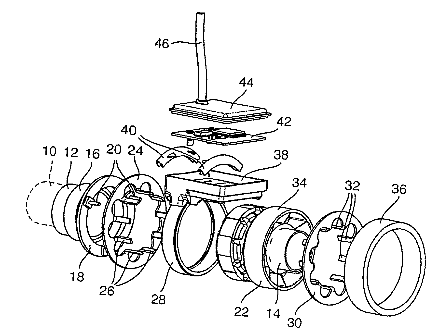
[0028]FIG. 1 illustrates a steering shaft, designated with 10, of a vehicle, wherein two shaft sections 12 and 14 are shown, which are connected to each other via a torsion bar spring (not shown) such that the two shaft sections 12 and 14 can be turned relative to each other when a torque is exerted on the steering shaft 10. The coupling of the two shaft sections 12 and 14 is e.g. clearly shown in DE 102 56 322 A1, the entire disclosure of which is hereby incorporated by reference. The shaft section 12 is provided with a holder for a multi-pole magnetic ring 16 which surrounds the steering shaft 10.

[0029]FIG. 1 moreover shows a threaded ring 18 which is screwed to a stator holder 22 via three screws 20 which are distributed about the periphery and project in an axial direction. A first stator element 24 is provided between the threaded ring 18 and the stator holder 22, which comprises axially projecting fingers 26 which extend over the multi-pole magnetic ring 16. The magnetic ring ...


PUM

PropertyMeasurementUnit
steering angleaaaaaaaaaa
torqueaaaaaaaaaa
temperaturesaaaaaaaaaa

Abstract

A device determines a torque that is exerted on a shaft, the shaft having a first shaft section and a second shaft section, the two shaft sections being rotatable in relation to one another. The device comprise a multi-pole magnetic ring and a stator support that is fixed to the second shaft section. Two stator elements are fixed to the stator support and each stator element has fingers that project in an axial or radial direction, are uniformly distributed at least over part of the circumference and are interspaced by gaps. The magnetic ring is situated between the fingers of one stator element and the fingers of the other stator element. A second magnetic ring is located on one of the two shaft sections and a magnetic sensor is mounted on one of the two shaft sections.

Description

[0001]True Translation of PCT / EP2005 / 000201 as filed on Jan. 12, 2005.[0002]This application is the national stage of PCT / EP2005 / 000201 filed on Jan. 12, 2005 and also claims Paris Convention priority of DE 20 2004 020 418.5 filed on Jan. 20, 2004, DE 20 2004 020 419.3 filed on Jan. 20, 2004, DE 20 2004 020 417.7 filed on Jan. 20, 2004, and DE 10 2004 023 801.4 filed on May 5, 2004,BACKGROUND OF THE INVENTION[0003]The invention concerns a device for determining a torque exerted on a shaft, wherein the shaft comprises a first shaft section and a second shaft section, the two shaft sections being rotatable relative to each other, and with a multi-pole magnetic ring which surrounds the first shaft section and is connected thereto, and a stator holder mounted to the second shaft section, wherein two stator elements are mounted to the stator holder, each stator element comprising fingers which project in an axially or radially outward direction, are uniformly distributed over at least pa...

Claims


Application Information

Patent Timeline
Patent Type & Authority Patents(United States)
IPC IPC(8): G01L3/00G01L3/10G01L5/22
CPCG01L5/221G01L3/101G01L3/104
Inventor JEREMS, FRANKRACHUI, DIRKFROEHLICH, EKKEHARTRUETZ, CHRISTIAN
Owner VALEO SCHALTER & SENSOREN
Why Eureka
Try Eureka