
Composite material and resin mold

a technology which is applied in the field of composite materials and resin molds, can solve the problems of large difference between the thermal expansion coefficient of inorganic materials and the material for molds, and it is difficult to singly use this organic material as the surface modification material, and achieve excellent unwettability and wear resistance. the effect of fluid resin

Inactive Publication Date: 2008-08-05
TOWA +1
View PDF5 Cites 3 Cited by
  • Summary
  • Abstract
  • Description
  • Claims
  • Application Information

AI Technical Summary

Benefits of technology

The present invention relates to a composite material that is used for a portion coming into contact with fluid resin. The composite material is made up of two materials that are hybridized with each other at a molecular level. The first material has excellent wear resistance against the fluid resin, while the second material has excellent unwettability against the hardened resin. The composite material exhibits excellent wear resistance and low adhesiveness to hardened resin. The composite material can be used for a resin mold, which is used for manufacturing moldings containing hardened resin. The composite material can be charged into the pores of the substrate, which allows for the removal of gas components from the fluid resin. The composite material can be recovered by grinding the surface of the substrate, exposing a new surface that contains the second material. Overall, the present invention provides a composite material that can be used for a variety of applications where wear resistance and low adhesiveness to hardened resin are important.

Problems solved by technology

First, the organic material such as polytetrafluoroethylene or silicone rubber employed for coating the mold surface is easily worn by the ceramic filler contained in the fluid resin. Therefore, it is difficult to singly use this organic material as the surface modification material for the mold.
Second, the wear-resistant inorganic hard material such as Cr, TiC or CrN constituting the film formed on the mold surface is so insufficient in unwettability against the fluid resin that releasability between the fluid resin and the mold surface is insufficient. Further, this inorganic material has a high elastic coefficient, and the difference between the thermal expansion coefficients of the inorganic material and the material for the mold is large. Therefore, remarkable thermal stress is caused on the interface between the film of the inorganic material and the mold surface in a cooling process after formation of the film. Thus, the film of the inorganic material may be separated from the mold surface due to stress repetitively caused during application of the mold.

Method used


Image

  • Composite material and resin mold
  • Composite material and resin mold
  • Composite material and resin mold

Examples


first embodiment

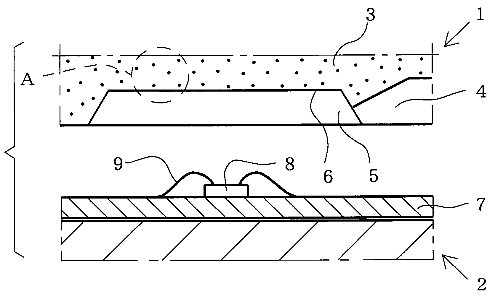
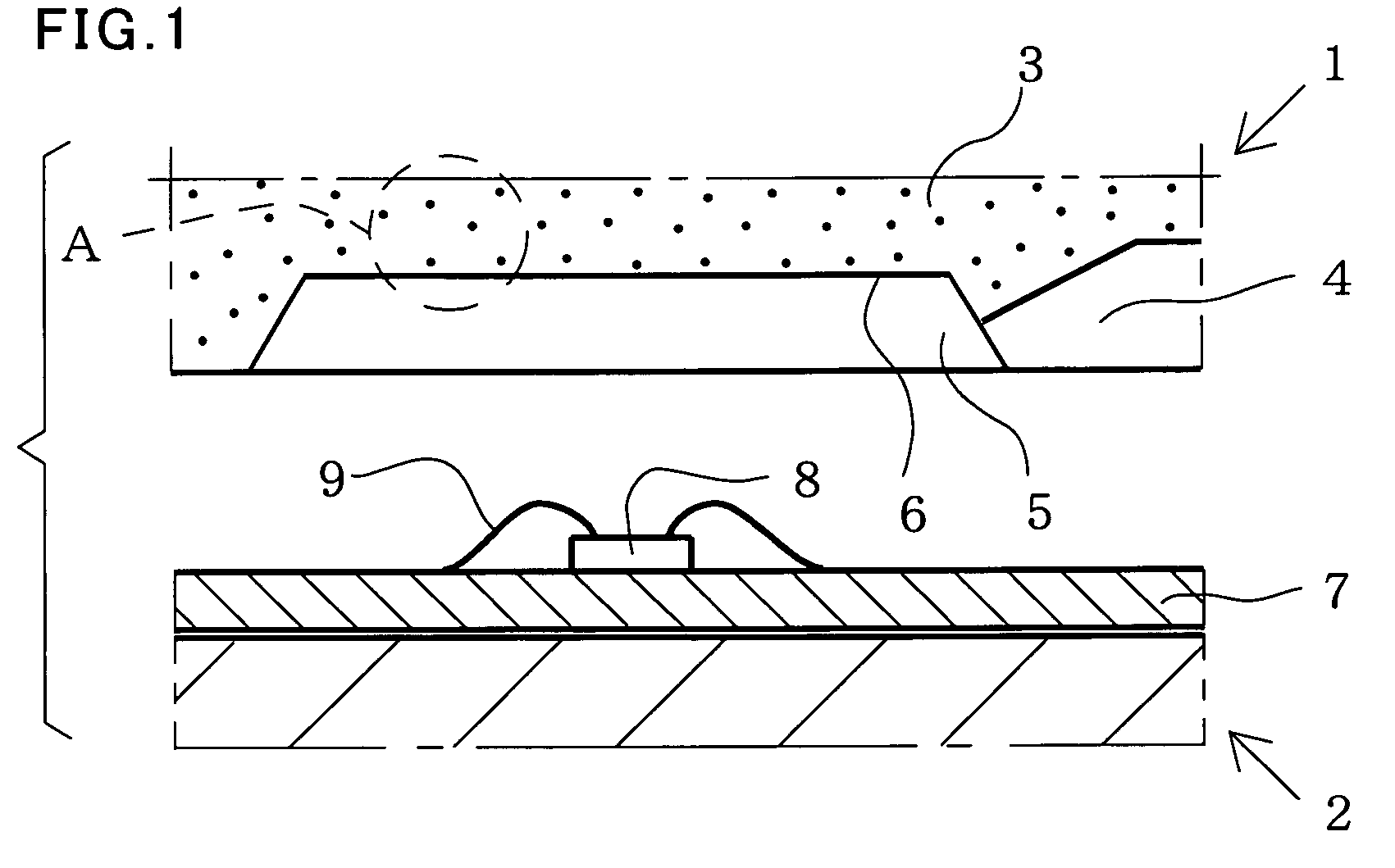
[0038]The composite material 3 and the resin mold according to the first embodiment of the present invention are described with reference to FIG. 1. FIG. 1 is a sectional view showing each of the resin molds according to the first to third embodiments of the present invention. The resin mold according to each of the embodiments described below is employed for sealing a chip mounted on a substrate with resin, for example. In this resin sealing, the resin mold stores the wired chip in a cavity thereof. Then, the resin mold is clamped for charging the cavity with fluid resin. Thereafter the fluid resin is hardened to form hardened resin. Consequently, a molding (package) having the substrate and the hardened resin is completed.

[0039]As shown in FIG. 1, a resin molding die according to the first embodiment is constituted of an upper mold section 1 and a lower mold section 2. The upper mold section 1 corresponds to the inventive resin mold. The composite material 3 according to the first...

second embodiment

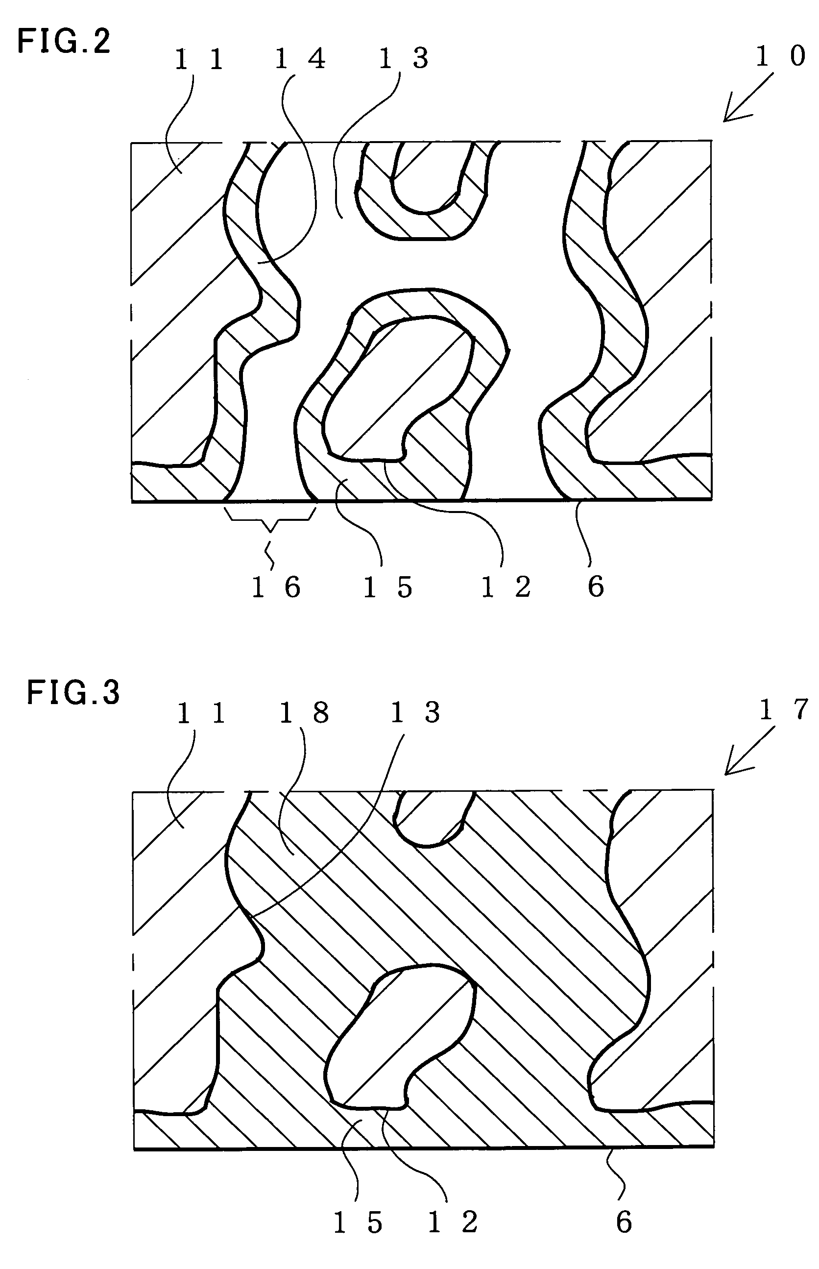
[0045]The composite material 10 and the resin mold according to the second embodiment of the present invention are described with reference to FIGS. 2 and 3. FIG. 2 is an enlarged sectional view of the composite material 10 according to the second embodiment, and FIG. 3 is an enlarged sectional view of a composite material 17 according to a modification of the second embodiment. Each of FIGS. 2 and 3 corresponds to an enlarged sectional view of a portion A shown in FIG. 1.

[0046]According to the second embodiment, the composite material 10 is used in place of the composite material 3 shown in FIG. 1, for constituting the upper section 1 in FIG. 1, i.e., the resin mold. The composite material 10 shown in FIG. 2 has a substrate 11 made of the first material described with reference to the first embodiment. The substrate 11, singly made of the first material such as zirconia (ZrO2), for example, in the second embodiment, may alternatively be made of a plurality of first materials.

[0047]...

third embodiment

[0059]The composite material 19 and the resin mold according to the third embodiment of the present invention are described with reference to FIG. 4. FIG. 4 is an enlarged sectional view of the composite material 19 according to the third embodiment, and FIG. 5 is an enlarged sectional view of a composite material 26 according to a modification of the third embodiment. Each of FIGS. 4 and 5 corresponds to an enlarged sectional view of the portion A shown in FIG. 1.

[0060]The composite material 19 shown in FIG. 4 has a substrate 20 of the first material described with reference to the first embodiment. The substrate 20, singly made of the first material such as zirconia (ZrO2), for example, in the third embodiment, may alternatively be made of a plurality of first materials. Further, the substrate 20 is provided with a large number of substantially linearly extending communicating holes (hereinafter referred to as one-dimensional communicating holes) 22 extending from a surface 21 of ...


PUM

PropertyMeasurementUnit
pore sizesaaaaaaaaaa
thicknessaaaaaaaaaa
thicknessaaaaaaaaaa

Abstract

A composite material used for a resin mold for forming hardened resin by hardening fluid resin is provided. The composite material comprises a first material having excellent wear resistance against the fluid resin and a second material having excellent unwettability against the fluid resin. The resin mold comprises a substrate of the first material, a large number of pores each provided to form an opening on a surface of the substrate opposite to the fluid resin and a film of the second material formed along the inner wall surface of each pore at least around the opening. Each of the large number of pores is a communicating hole connecting the surface opposite to the fluid resin and the remaining surface with each other. Therefore, releasability between a mold surface and the hardened resin and wear resistance of the composite material against the fluid resin can be improved.

Description

[0001]This nonprovisional application is based on Japanese Patent Application No. 2004-004543 filed with the Japan Patent Office on Jan. 9, 2004, the entire contents of which are hereby incorporated by reference.BACKGROUND OF THE INVENTION[0002]1. Field of the Invention[0003]The present invention relates to a composite material composed of different materials and a resin mold of this composite material used for manufacturing a molding by hardening fluid resin.[0004]2. Description of the Background Art[0005]Transfer molding or injection molding is employed for conventional resin molding. According to this method, fluid resin is charged into a cavity provided in a resin mold. Thereafter the charged fluid resin is hardened to form hardened resin. Consequently, a molding having the hardened resin is formed. In the aforementioned method, releasability between the hardened resin and the surface of the mold must be so improved that the molding can be easily taken out.[0006]For example, an ...

Claims


Application Information

Patent Timeline
Patent Type & Authority Patents(United States)
IPC IPC(8): B29C33/40B29C45/02B29C33/38B29C45/14B29C45/37C08J5/00C08K3/22
CPCB29C33/40B29C33/56C08J5/00B29C45/37B29C45/14639B29C45/02
Inventor KUNO, TAKAKIMAEDA, KEIJINOGUCHI, YOSINORIKITAOKA, SATOSHIKAWASHIMA, NAOKI
Owner TOWA
Learn More