System and method for a protected optical access ring network

a protection network and optical access technology, applied in multiplex communication, transmission monitoring, instruments, etc., can solve the problems of many fiber connections terminating in the same central office, consuming a considerable amount of power, and point-to-point structure, and achieves simple and robust construction, simple and robust effect, and removal of the vulnerability of the ring topology to failur

Inactive Publication Date: 2008-08-05
LUCENT TECH INC
View PDF6 Cites 12 Cited by
  • Summary
  • Abstract
  • Description
  • Claims
  • Application Information

AI Technical Summary

Benefits of technology

[0008]In this manner, an optical access network according to the principles of the invention combines expandability and ease of collision avoidance without incurring the penalty of sensitivity to individual end-point failures. More specifically, since the optical access network uses the ring topology, it has the advantage of simple collision avoidance and the fact that each network unit acts as a repeater. The protection switch, however, removes the vulnerability of the ring topology to failure of individual network units by switching out failed network units while maintaining the continuity of the ring and in one form of the invention it also protects against possible unauthorized or malicious usage, by switching out failed network units while maintaining the continuity of the ring. Moreover, the protection switch can be of simple and robust construction, requiring little in the way of maintenance and power requirements.

Problems solved by technology

However, the point-to-point structure, in some circumstances, suffers from the disadvantage that there may be very many fiber connections terminating in the same central office.
Also, an optical switch is a sophisticated piece of apparatus, consuming a considerable amount of power and requiring management to monitor and, when necessary, rectify performance, so there are disadvantages in locating such a switch outside the central office.
Furthermore, such equipment represents a considerable investment, and levels of use at the outer fringes of the network are likely to be low.
However, the number of user end-points that can be accommodated is limited because of the use of power splitters; the more optical network units there are, the less the power that reaches each one.
However, although the ring topology is useful for computer networks, where all the network units are accessible to central management, it is not currently favored for optical access networks, because the failure of one user's network unit causes a break in the ring and adversely affects all the users on the ring.
Also, unauthorized or malicious usage is something that known ring topology networks cannot protect against.

Method used


Image

  • System and method for a protected optical access ring network
  • System and method for a protected optical access ring network
  • System and method for a protected optical access ring network

Examples


Embodiment Construction

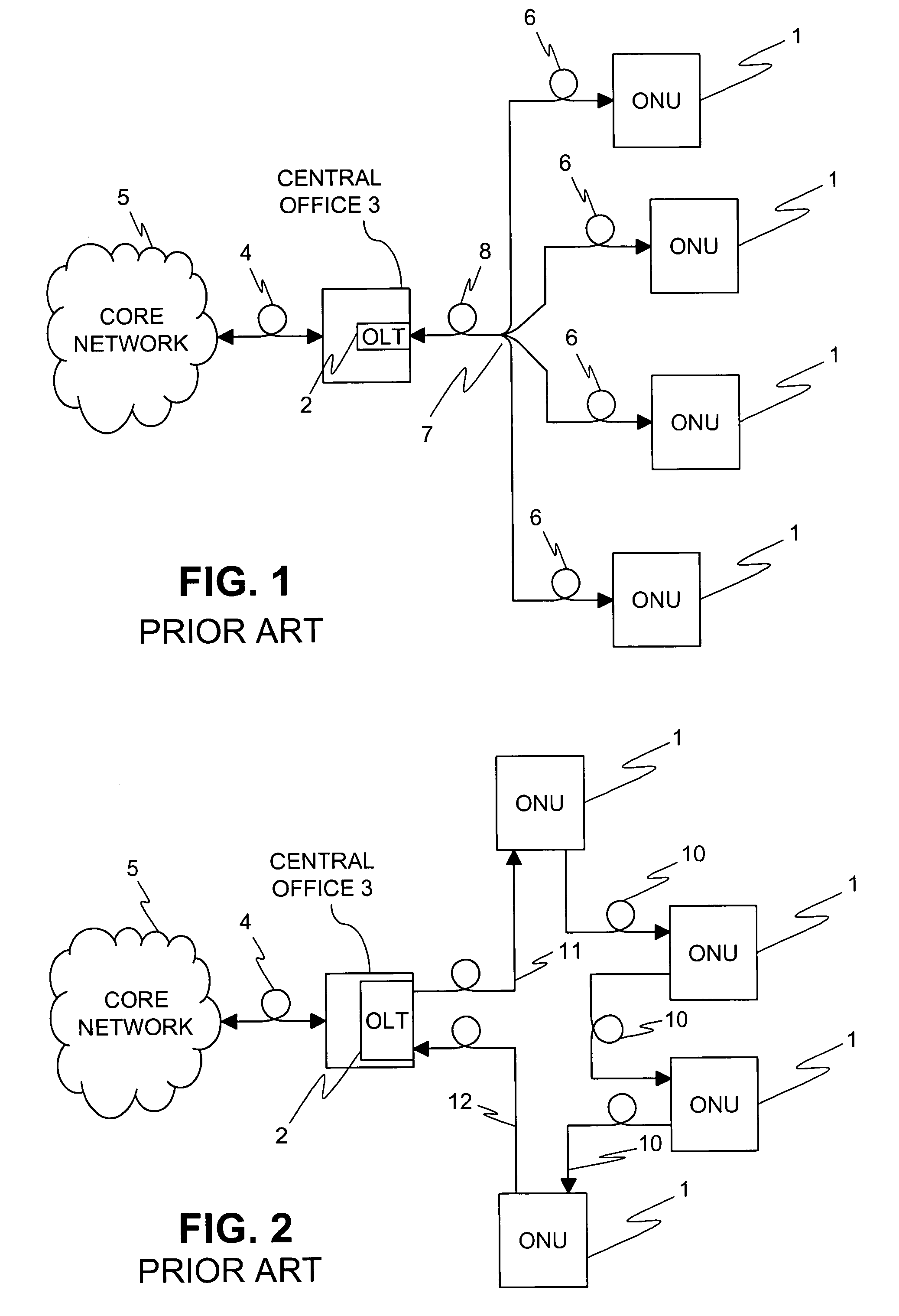
[0018]FIG. 1 shows a number of optical network units 1, situated at or near customer premises, connected to an optical line terminal 2 situated in a central office 3. The central office 3 is further connected via an optical fiber connection 4 to a core network 5. The connection between the optical network units 1 and the optical line terminal 2 is a so-called tree-and-branch topology. This topology consists of a plurality of individual optical fibers 6, one connected to each of the optical network units 1 and connected via a splitter / combiner 7 to a single optical fiber 8, which is connected to the optical line terminal 2. Thus, signals from optical line terminal 2 proceed via single optical fiber 8 to splitter / combiner 7 where they are divided and sent to all of the optical network units 1 via individual optical fibers 6. Since the power of the outgoing signals is divided by the splitter / combiner 7, the power reaching the optical network units 1 via the individual optical fibers 6 ...


PUM

PropertyMeasurementUnit
poweraaaaaaaaaa
timeaaaaaaaaaa
distanceaaaaaaaaaa

Abstract

An optical access network employs a ring topology in which connections between the network units and between the network units and the optical line terminal are via a protection switch. The protection switch monitors connections from the optical network units to detect a loss of signal and, on detecting a loss of signal from an optical network unit, switches the respective optical network unit out of the ring, thus maintaining continuity of the ring topology.

Description

TECHNICAL FIELD[0001]This invention relates generally to optical access networks and, more particularly, to protection switching in such networks.BACKGROUND OF THE INVENTION[0002]Optical access networks provide optical fiber connections between public networks and end-users. They offer an important solution for the implementation of broadband access networks. They combine a large transport capacity with the capability of serving a wide geographical area. They support connections from central network entities like local exchanges to residential network units and thus can be used to deploy concepts like fiber-to-the-home (FTTH) and fiber-to-the-curb (FTTC). Passive optical networks (PONs) have been studied for many years but, until now, successful commercial deployment was growing slowly.[0003]One possible structure that has been suggested for optical access networks is the point-to-point structure, in which a separate fiber connection is provided between a central office and an optic...

Claims


Application Information

Patent Timeline
Patent Type & Authority Patents(United States)
IPC IPC(8): H04B10/08G02F1/00H04B10/20H04J14/00H04Q11/00
CPCH04Q11/0067H04Q2011/0094H04Q2011/0092H04Q2011/0081
Inventor WELLEN, JEROEN SIEBRAND
Owner LUCENT TECH INC
Why Eureka
Try Eureka