Dual-input power converter and control methods thereof

a power converter and dual-input technology, applied in the field of dual-input power converters and control methods thereof, can solve the problems of slowing down the total conversion efficiency and gradual decay of the battery voltage as it is used, and achieve the effect of improving the conversion efficiency of the converter

Inactive Publication Date: 2008-08-12
RICHTEK TECH
View PDF9 Cites 100 Cited by
  • Summary
  • Abstract
  • Description
  • Claims
  • Application Information

AI Technical Summary

Benefits of technology

[0009]By using two power stages having a common low-side element and a controller to select one of them to drive, a power converter may produce an output voltage by only one stage conversion, and the conversion efficiency thereof is improved significantly.

Problems solved by technology

However, the battery voltage gradually decays as it is used.
As a result, the total conversion efficiency is lowed down after the two-stage power conversion.

Method used


Image

  • Dual-input power converter and control methods thereof
  • Dual-input power converter and control methods thereof
  • Dual-input power converter and control methods thereof

Examples


Embodiment Construction

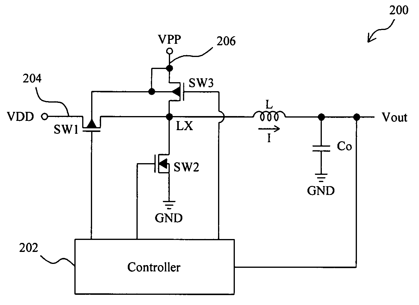
[0025]As an embodiment of the present invention, FIG. 2 shows a circuit diagram of a dual-input power converter 200, which comprises two power stages and a controller 202 to drive thereto. The first power stage includes transistors SW1 and SW2, and the second power stage includes transistors SW3 and SW2. In particular, the transistor SW2 serves as a common low-side element of the two power stages and thereby, it behaves as a low-side element in association with the transistor SW1 for operating a first converter in some time and behaves as a low-side element in association with the transistor SW3 for operating a second converter in another time. Additionally, an inductor L and a capacitor Co also serve as common devices for constructing two converters. Namely, the transistors SW1 and SW2, inductor L, capacitor Co and controller 202 may constitute a first buck converter to convert a first input voltage VDD coupled to a first input 204 to the output voltage Vout, and the transistors SW...


PUM


Abstract

A dual-input power converter comprises two power stages using a common low-side element, a first input for coupling a first input voltage to the first power stage, a second input for coupling a second input voltage to the second power stage, and a controller for driving the first and second power stages to convert the first or second input voltage to an output voltage.

Description

FIELD OF THE INVENTION[0001]The present invention relates generally to a power converter and, more particularly, to a dual-input power converter and control methods thereof.BACKGROUND OF THE INVENTION[0002]Generally, a switching-mode power converter converts an input voltage to an output voltage by alternatively switching a pair of high-side and low-side elements coupled with the input voltage. In a synchronous power converter, the high-side and low-side elements both are switches such as MOS transistors, and in an asynchronous power converter, the high-side and low-side elements are a switch and a diode, respectively. Additionally, power converters are classified into two types, boost converter and buck converter, depending on the way of producing the output voltage by boosting or bucking the input voltage.[0003]In most portable electronic products, alkaline and lithium batteries are used for power source. However, the battery voltage gradually decays as it is used. To obtain a sta...

Claims


Application Information

Patent Timeline
Patent Type & Authority Patents(United States)
IPC IPC(8): H02M3/16H02J1/00H02M1/08
CPCH02M3/158H02M1/10
Inventor PAI, CHUNG-LUNG
Owner RICHTEK TECH
Why Eureka
Try Eureka