

Rotating electric machine
a technology of rotating electric machines and rotating parts, which is applied in the direction of dynamo-electric machines, magnetic circuit rotating parts, magnetic circuit shape/form/construction, etc., can solve the problem of not producing rotational flux, and achieve the effect of increasing torque and torque and output thereof, and suppressing torque fluctuation
- Summary
- Abstract
- Description
- Claims
- Application Information
AI Technical Summary
Benefits of technology
Problems solved by technology
Method used
Image

Examples
first embodiment
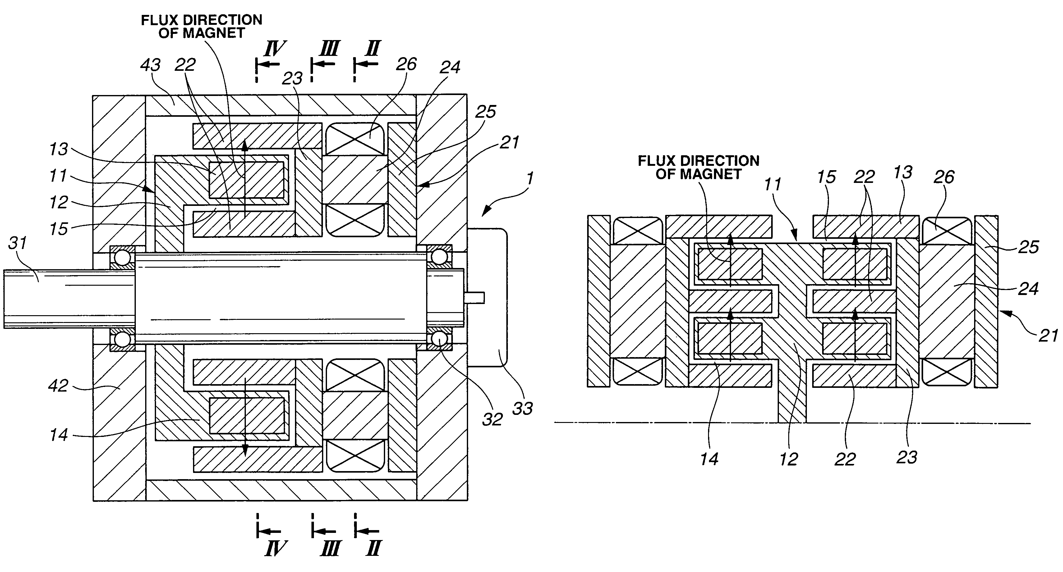
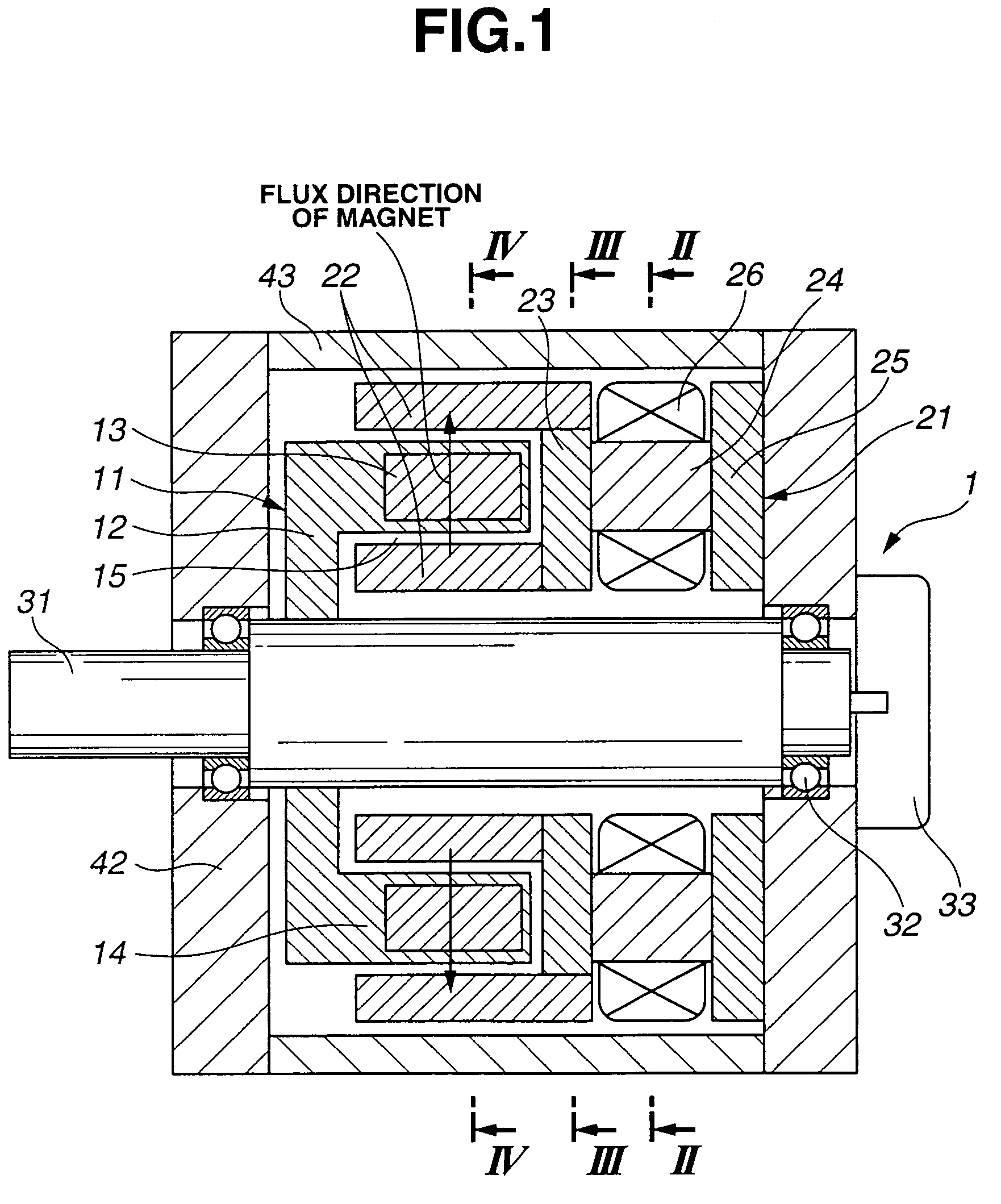
[0019]As shown in FIGS. 1 through 4, rotating electric machine 1 comprises a rotor 11, a stator 21, a rotation shaft 31 and a casing 41. Rotor 11 has a rotor core 12 and a plurality of permanent magnets 13 provided in rotor core 12. The number of permanent magnets 13 denotes the number of poles of rotor 11. As shown in FIG. 4, there are provided 8 permanent magnets 13 circumferentially around rotation shaft 31, and therefore rotating electric machine 1 of the first embodiment is of a 8-pole type. That is, the array of permanent magnets 13 are circular around rotation shaft 31. Permanent magnets 13 are provided in a cylindrical tip portion of rotor core 12 and constructs a rotor projecting portion 14.
[0020]A direction of flux of permanent magnets-13 is directed in the diametrical direction of rotating electric machine 1 as shown by an arrow in FIG. 1. That is, in this first embodiment, the direction of the flux of permanent magnets 13 is a radial direction extending from the center o...
second embodiment
[0024]FIG. 5 is a partial cross sectional view of rotating electric machine 1 according to the present invention. In FIG. 5, elements as same as those shown in FIGS. 1 through 4 are denoted by the same reference numerals and the explanation thereof is omitted herein. Rotating electric machine 1 shown in FIG. 5 is constructed such that rotor 11 is formed in the shape of character T in cross section including a center axis of rotating electric machine 1, and each rotor element per each pole of rotor 11 has a plurality of permanent magnets 13. Herein, each rotor element of rotor 11 has two permanent magnets 13. More specifically, as shown in FIG. 5, rotor core 12 is constructed such that a disc-shaped member is connected to rotation shaft, that a center portion of a cylindrical member is connected to an outer periphery of the disc-shaped member, and that permanent magnets 13 are embedded in both end portions of the cylindrical member. That is, each rotor element of rotor 11 has two per...
third embodiment
[0025]FIG. 6 is a partial cross sectional view of rotating electric machine 1 according to the present invention. In FIG. 6, elements as same as those shown in FIGS. 1 through 4 are denoted by the same reference numerals and the explanation thereof is omitted herein. Rotating electric machine 1 shown in FIG. 6 is constructed such that rotor 11 is formed in the shape of a cross shape in cross section including the center axis of rotating electric machine 1, and each rotor element per each pole of rotor 11. Herein, each rotor element of rotor 11 has a plurality of permanent magnets 13, and each element has four permanent magnets 13. Two stators 21 are disposed along the axial direction. Two rotor projecting portions 14, which extend along the axial direction, are respectively sandwiched by stator core tip portions 22 of two stators 21. Further, a top end of each inner stator core tip portion 22 extends inwardly toward the center axis so as to sandwich magnets 13 embedded in inner side...
PUM
 Abstract
Description
Claims
Application Information