Gimbaled dragonian antenna

Active Publication Date: 2008-08-12
THE BOEING CO
View PDF8 Cites 14 Cited by
  • Summary
  • Abstract
  • Description
  • Claims
  • Application Information

AI Technical Summary

Benefits of technology

[0011]A better understanding of the above and many other features and advantages of the present invention may be obtained from a consideration of the detailed description of the exemplary embodiments thereof b

Problems solved by technology

This large number of reflectors requires complicated design, assembly, and align

Method used


Image

  • Gimbaled dragonian antenna
  • Gimbaled dragonian antenna
  • Gimbaled dragonian antenna

Examples


Example

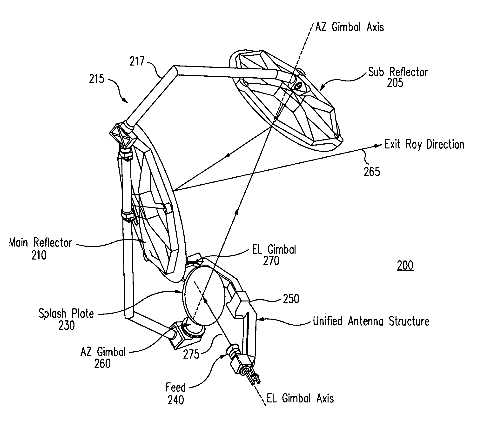
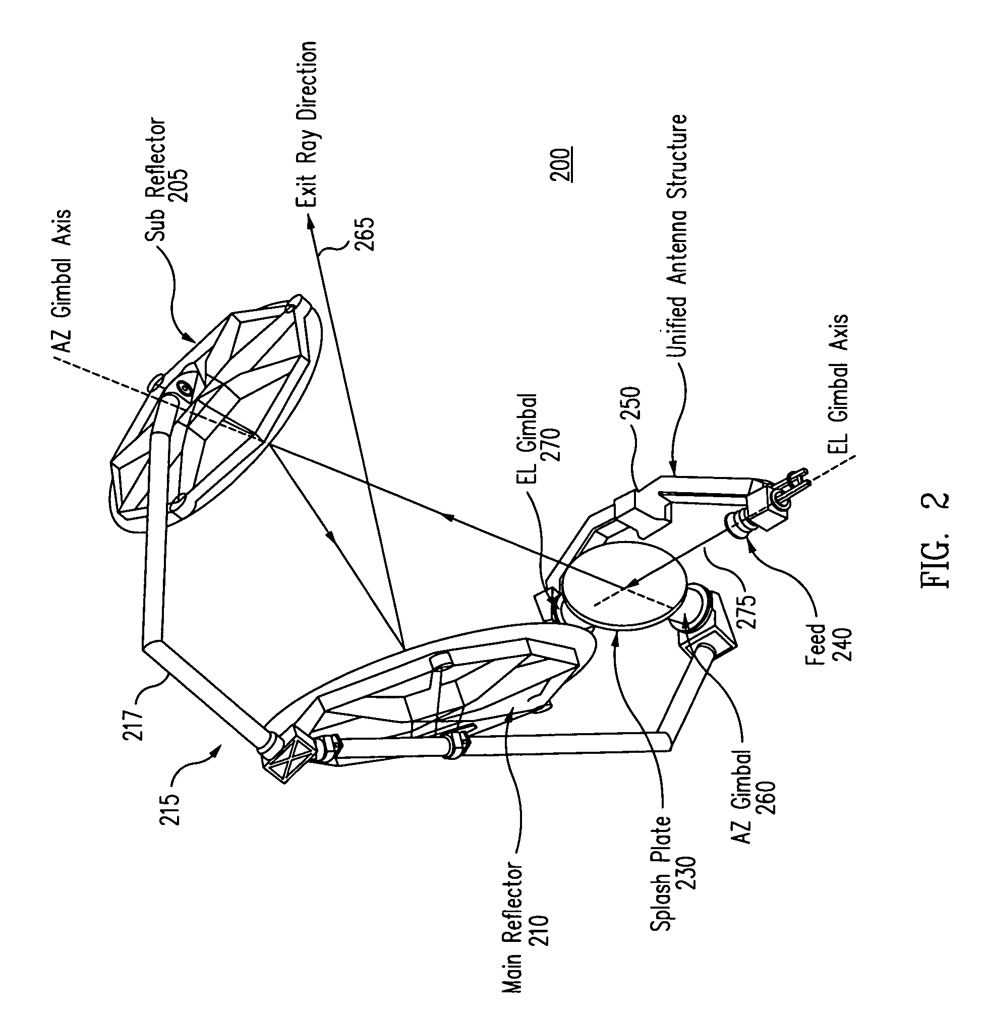
[0018]To avoid the aforementioned problems in the prior art, a beam waveguide gimbaled reflector antenna is provided that includes as few as three mirror elements. Turning now to FIG. 2, an isometric view of an exemplary embodiment of a beam waveguide gimbaled reflector antenna 200 is illustrated. A hyperbolic sub-reflector 205 and a parabolic main reflector 210 form a Dragonian antenna sub-system 215 supported by a frame 217. As known in the art, Dragonian antennas are also referred to as side-fed offset Cassegrain antennas. A flat plate (splash plate) reflector 230 (reflects an RF beam from a feed such as a feed horn 240 towards sub-reflector 205.

[0019]Feed horn 240 mounts on an antenna structure 250 that forms the mounting reference for antenna 200. For example, in a space-based application, antenna structure 250 would be mounted to the spacecraft. Frame 217 for Dragonian antenna sub-system 215 mounts to an azimuth gimbal 260 that is also coupled to flat reflector 230. The spatia...


PUM


Abstract

In one embodiment, a gimbaled reflector antenna is provided that includes: a Dragonian antenna having a sub-reflector and a main reflector; a feed; a third reflector adapted to reflect a beam from the feed to the sub reflector; an azimuth gimbal adapted to rotate the Dragonian antenna with respect to the third reflector; and an elevation gimbal adapted to rotate the flat reflector with respect to the feed.

Description

RELATED APPLICATIONS[0001]This patent application claims the benefit of U.S. Provisional Patent Application No. 60 / 675,146, filed on Apr. 27, 2005 and entitled GIMBALED DRAGONIAN ANTENNA. The entire contents of this provisional patent application are hereby expressly incorporated by reference.STATEMENT REGARDING FEDERALLY SPONSORED RESEARCH OR DEVELOPMENT[0002]This invention was made with Government support under contract number FA8808-04-C-0022 awarded by the U.S. Air Force. The Government has certain rights in this invention.TECHNICAL FIELD[0003]This invention relates to antennas, and more particularly to a gimbaled reflector antenna.BACKGROUND[0004]Gimbaled reflector antennas provide a high gain signal path over a wide field of regard extending beyond the beam width of a fixed antenna of equivalent design. This high gain signal path is provided by mechanically steering the beam to a desired location through appropriate actuation of the associated gimbals. In this fashion, a gimba...

Claims


Application Information

Patent Timeline
IPC IPC(8): H01Q13/00
CPCH01Q19/192H01Q19/191
Inventor BALDAUF, JOHN E.LEE, ERIC D.PARK, BRIAN M.DIXON, JOEL R.
Owner THE BOEING CO
Why Eureka
Try Eureka