Dustproof lens assembly

a technology of lens assembly and dustproof coating, which is applied in the field of optical lens assembly, can solve the problems of still dust on the lens assembly and image sensor, and achieve the effect of cleaning the environment of the image sensor

Active Publication Date: 2008-08-12
AO ETHER
View PDF3 Cites 12 Cited by
  • Summary
  • Abstract
  • Description
  • Claims
  • Application Information

AI Technical Summary

Benefits of technology

[0007]The primary objective of the present invention is to provide a dustproof lens assembly, which may prevent dust between the barrel and the holder from dropping onto the image sensor.
[0008]According to the objective of the present invention, a dustproof lens assembly includes a holder and a barrel. The holder has an inner space, in which an image sensor is received. The holder and the barrel have connecting portions for engagement and a block portion is provided between the inner space and the connecting portions to block dust between the first connecting portion and the second connecting portion out of the inner space of the holder and give the image sensor a clean environment.

Problems solved by technology

As a result, this lens assembly still has dust on the image sensor.

Method used


Image

  • Dustproof lens assembly
  • Dustproof lens assembly
  • Dustproof lens assembly

Examples


Embodiment Construction

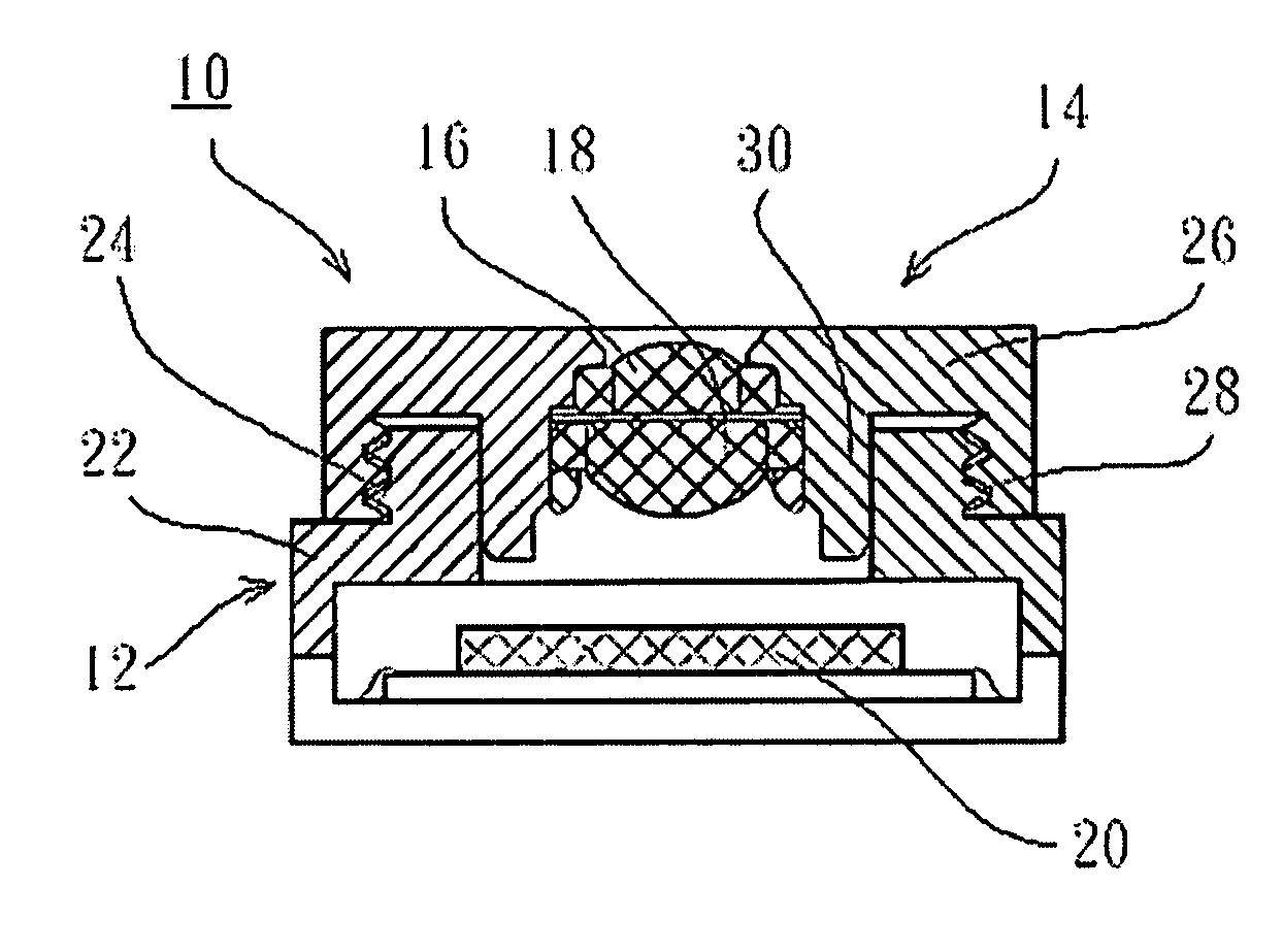
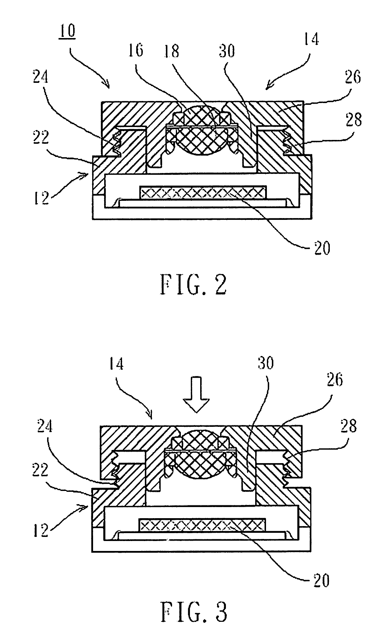
[0013]As shown in FIG. 2 to FIG. 3, a dustproof lens assembly 10 of the first preferred embodiment of the present invention, which is mounted on an image sensor 20, includes a holder 12 and a barrel 14.

[0014]The holder 12 has a hollow member 22 with an inner space therein and a first connecting portion 24 oh a top thereof. The first connecting portion 24 has an outer threaded section on a circumference thereof.

[0015]The barrel 14 has a hollow member 26 and two lenses 16 and 18 mounted in the hollow member 26. The hollow member 26 has a second connecting portion 28 on a bottom thereof. The second connecting portion 28 is complementary to the first connecting portion 24, which has an inner threaded section to be meshed with the outer threaded section of the first connecting portion 24. The hollow member 26 further has a block portion 30, which is an annular protrusion on the bottom of the hollow member 26 within the second connecting portion 28. A distance between the second connectin...


PUM


Abstract

A dustproof lens assembly includes a holder and a barrel. The holder has an inner space, in which an image sensor is received. The holder and the barrel have connecting portions for engagement and a block portion is provided between the inner space and the connecting portions to block dust between the first connecting portion and the second connecting portion out of the inner space of the holder and give the image sensor a clean environment.

Description

BACKGROUND OF THE INVENTION[0001]1. Field of the Invention[0002]The present invention relates generally to an optical lens assembly, and more particularly to a dustproof lens assembly.[0003]2. Description of the Related Art[0004]FIG. 1 shows an image catch unit 1 of an electronic product, such as digital camera, digit personal assistant (PDA), and mobile phone, includes an optical lens assembly 2 and an image sensor 3. The image sensor 3 is electrically connected to a flexible printed circuit board (FPCB) 4, and the optical lens assembly 2 is mounted on the image sensor 3. The optical lens assembly 2 includes a holder 5, on a bottom of which the image sensor 3 is provided, a barrel 6 mounted on the holder 5 and lens 7 mounted in the barrel 6. Light is emitted to the image sensor 3 through the lens 7 and the holder 5 to generate an image signal. The FPCB 4 receives the image signal and transmits it to a circuit board of the electronic product.[0005]The barrel 6 and the holder 5 have ...

Claims


Application Information

Patent Timeline
Patent Type & Authority Patents(United States)
IPC IPC(8): G02B7/02
CPCG02B7/02H04N5/2257H04N5/2254G02B27/0006H04N23/52H04N23/57H04N23/55
Inventor LIU, CHUNXI
Owner AO ETHER
Why Eureka
Try Eureka