Eye detection apparatus and image display apparatus

a technology of image display and eye detection, which is applied in the field of eye detection apparatus, can solve the problems of inability to accurately detect the position of the observer's pupil using the aforementioned conventional detection method, and the size of the display optical system will increase with the increase in the pupil diameter

Inactive Publication Date: 2008-08-19
CANON KK
View PDF7 Cites 172 Cited by
  • Summary
  • Abstract
  • Description
  • Claims
  • Application Information

AI Technical Summary

Problems solved by technology

When an observer wears a head mounted display (which will be abbreviated as HMD hereinafter) and observes an image, if the designed optical axis of the display optical system and the direction of the line of sight of the observer do not coincide with each other, there is a possibility that when the observer moves his / her eye to observe a peripheral portion of the image, the eye deviates from the pupil diameter of the display optical system to cause eclipse or spoil strength of observed images, though it is possible to observe the central portion of the image.
However, the size of the display optical system will increase with the increase in the pupil diameter.
In cases where the position of the eye is not in the predetermined area, the position of the pupil of the observer cannot be detected accurately using the aforementioned conventional detecting method.
Moreover, while there is a trend of widening the angle of field of the HMD recently, the above-described conventional detection method cannot cope with the widening of the angle of view, since its detection area is limited.

Method used


Image

  • Eye detection apparatus and image display apparatus
  • Eye detection apparatus and image display apparatus
  • Eye detection apparatus and image display apparatus

Examples


first embodiment

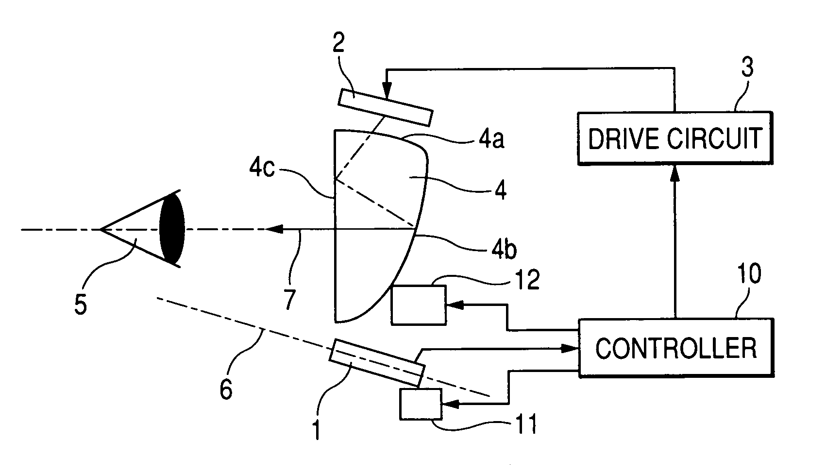
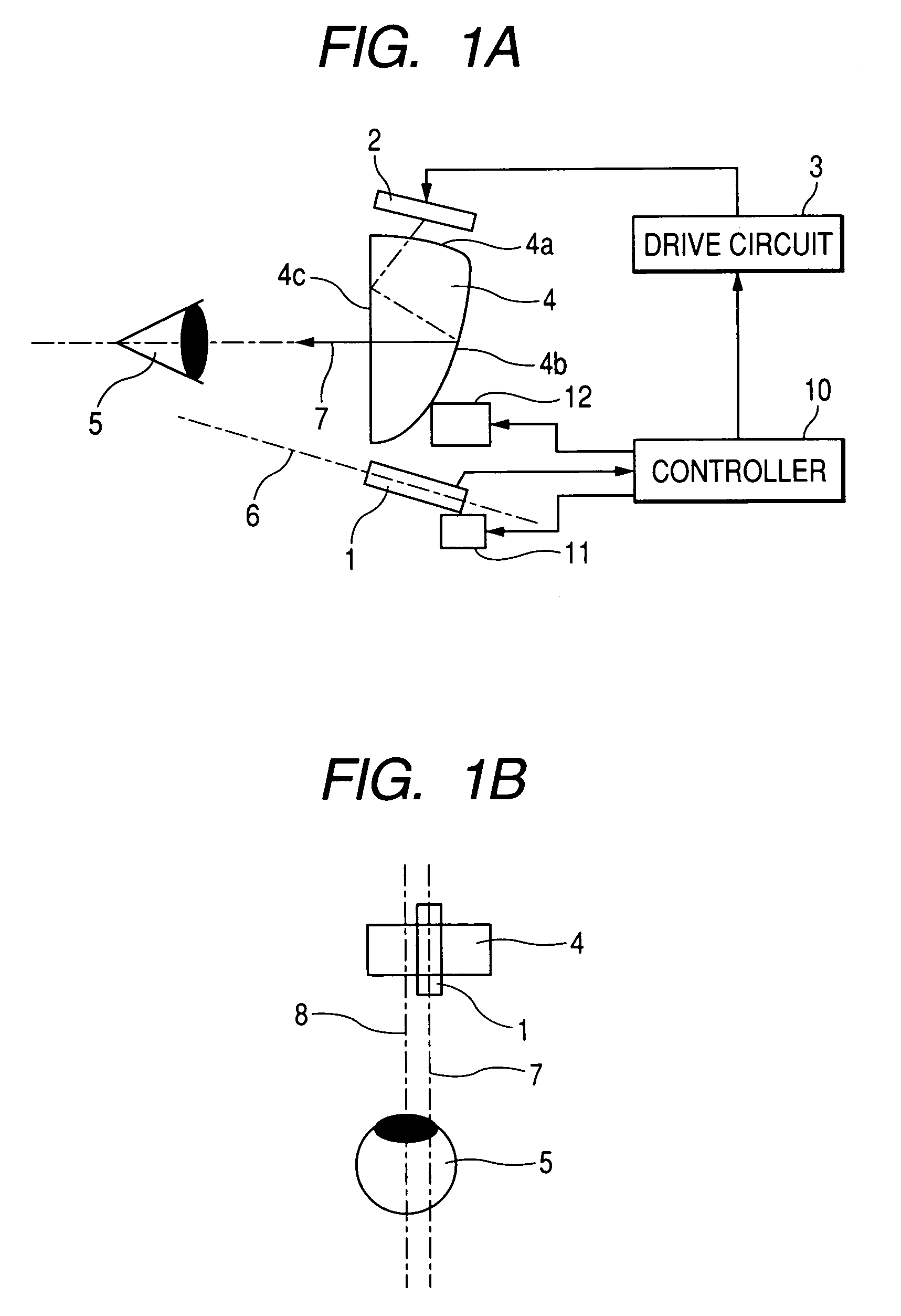
[0039]An image display apparatus (HMD) according to the first embodiment of the present invention will be described. FIG. 1A is a side view schematically showing the inner structure of the HMD according to this embodiment. FIG. 1B is a top view of the inner structure.

[0040]In the HMD of this embodiment, as shown in FIG. 1B, the optical axis of an image taking unit and the optical axis of a display optical system are in the same plane, and horizontal displacement (displacement in the right-and-left direction in FIG. 1B) of the optical axis position (or the position of the emerging optical axis) of the display optical system relative to the position of a pupil (or the position of the line of sight) of the observer is to be detected.

[0041]Reference numeral 1 designates an image taking unit which has an image pickup element such as a CCD sensor or a CMOS sensor and an optical system for forming an image of an eye of an observer on the image pickup element. Reference numeral 2 designates...

second embodiment

[0087]Next, an HMD according to a second embodiment of the present invention will be described. The HMD of this embodiment is adapted to detect the direction of line of sight of the observer.

[0088]FIGS. 9A and 9B schematically show the basic structure of the HMD of this embodiment. FIG. 9A is a side view schematically showing the inner structure of the HMD according to this embodiment. FIG. 9B is a top view of the inner structure. In FIGS. 9A and 9B, the components same as those in the first embodiment are designated by the same reference signs and descriptions thereof will be omitted.

[0089]In this embodiment, the image taking unit 1 and the display optical system 4 are disposed in such a way that the optical axis 6 of the image taking unit 1 and the emerging optical axis 7 of the display optical system 4 are in the same plane and substantially parallel to each other in that plane.

[0090]The image taking unit 1 and the display optical system 4 are adapted to be moved integrally by a ...

third embodiment

[0120]Next, an HMD according to the third embodiment of the present invention will be described. In the HMD of this embodiment, an image display element and a display optical system etc. are provided for each of both eyes of the observer, and the interpupillary distance of the observer can be detected.

[0121]FIG. 14A is a side view schematically showing the inner structure of the HMD according to this embodiment. FIG. 14B is a top view of the inner structure. In FIGS. 14A and 14B, the members same as those in the first and second embodiments are designated by the same reference signs and descriptions thereof will be omitted.

[0122]The image taking unit 1 and the display optical system 4 are disposed in such a way that the optical axis 6 of the image taking unit 1 and the emerging optical axis 7 of the display optical system 4 are in the same plane. In addition, the image taking unit 1 and the display optical system 4 may be disposed in such a way that the optical axis 6 and the emergi...


PUM


Abstract

What is disclosed is an eye detection apparatus which can detect the pupil position accurately. The apparatus has an image taking unit that picks up an image of an eye and a pupil detection unit that detects the position of the pupil in the eye based on an image picked up by the image taking portion. The pupil detection unit determines the pupil position based on images picked up by the image taking unit in a plurality of states.

Description

BACKGROUND OF THE INVENTION[0001]1. Field of the Invention[0002]The present invention relates to an eye detection apparatus provided in, for example, a head mount display to be mounted on the head of a user, for detecting the position of a pupil of the user.[0003]2. Description of Related Art[0004]When an observer wears a head mounted display (which will be abbreviated as HMD hereinafter) and observes an image, if the designed optical axis of the display optical system and the direction of the line of sight of the observer do not coincide with each other, there is a possibility that when the observer moves his / her eye to observe a peripheral portion of the image, the eye deviates from the pupil diameter of the display optical system to cause eclipse or spoil strength of observed images, though it is possible to observe the central portion of the image.[0005]To make the HMD suitable for an increased number of observers, it is necessary to make the pupil diameter of the display optica...

Claims


Application Information

Patent Timeline
Patent Type & Authority Patents(United States)
IPC IPC(8): G02B27/14A61B3/10G02B3/02H04N5/262
CPCA61B3/0008A61B3/11G02B27/0093A61B3/113G02B17/086G06V40/19
Inventor URAKAWA, TAKASHISAITO, YOSHIHIROITAKAGI, AKINARI
Owner CANON KK
Why Eureka
Try Eureka