Arrangement for controlling fluid jets injected into a fluid stream

a technology of fluid flow and arrangement, which is applied in the direction of liquid transfer devices, lighting and heating apparatus, combustion types, etc., can solve the problems of increasing entrainment, not achieving significant enhancement in mixing relative to round holes, and no shape that offers significant improvement over round orifice shapes, etc., to achieve strong plume-plume interaction and mixing, and the magnitude of lifting force is altered. , the effect of strong influence on the penetration of the j

Active Publication Date: 2008-08-26
RTX CORP
View PDF5 Cites 4 Cited by
  • Summary
  • Abstract
  • Description
  • Claims
  • Application Information

AI Technical Summary

Benefits of technology

[0016]The orifice from which the primary fluid is emitted is given a streamlined, airfoil-like shape to create (in an extruding fashion) a steamlined jet having a wing-like form in the vicinity of the orifice. The term “streamlined” refers to a body dominated by frictional drag, as opposed to pressure drag. When the wing-like jet is placed at an angle of attack in the secondary fluid cross-stream, a strong tilting force develops on the jet, much like the well known lifting force on a solid wing, causing the jet to bend away from the plane defined by the initial injection direction and the cross-stream direction. By varying the angle of attack, the magnitude of the lifting force is altered, and the penetration of the jet is strongly affected. Additionally, the lift force creates circulatory-flow (i.e. single-sided vorticity) around the jet that maintains itself far downstream of the jet orifice. Both of these effects strongly affect the penetration, mixing, and interaction of multiple fluid-wings. For a given airfoil-like orifice shape, the variation of angle of attack provides a strong control authority over the jet penetration depth. Since the angle of attack is a geometric quantity, it is independent of the exit velocity of the jet, and, thus, provides a control of jet penetration that is independent of jet exit velocity.

Problems solved by technology

Optimizing correlations were developed but a significant enhancement in mixing relative to round holes was not achieved.
Azimuthal non-uniformity at the jet inlet is naturally unstable and introduces streamwise vorticity which increases entrainment for axisymmetric flows, however in a crossflow configuration the vorticity field is dominated by the bending imposed by the mainstream.
While slanted slots have provided some reduction in penetration depth, no shapes have been reported that offer significant improvements over the round orifice shape.
The lack of a mechanism for the control of plume penetration depth that is independent of the exit jet velocity is a shortcoming that forces compromises into the design of industrial systems.
Consequently, when multiple plumes are present, the counter-rotating vortices produce a weak interaction between neighboring plumes emitted from near-by orifices, leading to relatively weak overall dispersion of the primary fluid.

Method used


Image

  • Arrangement for controlling fluid jets injected into a fluid stream
  • Arrangement for controlling fluid jets injected into a fluid stream
  • Arrangement for controlling fluid jets injected into a fluid stream

Examples


Embodiment Construction

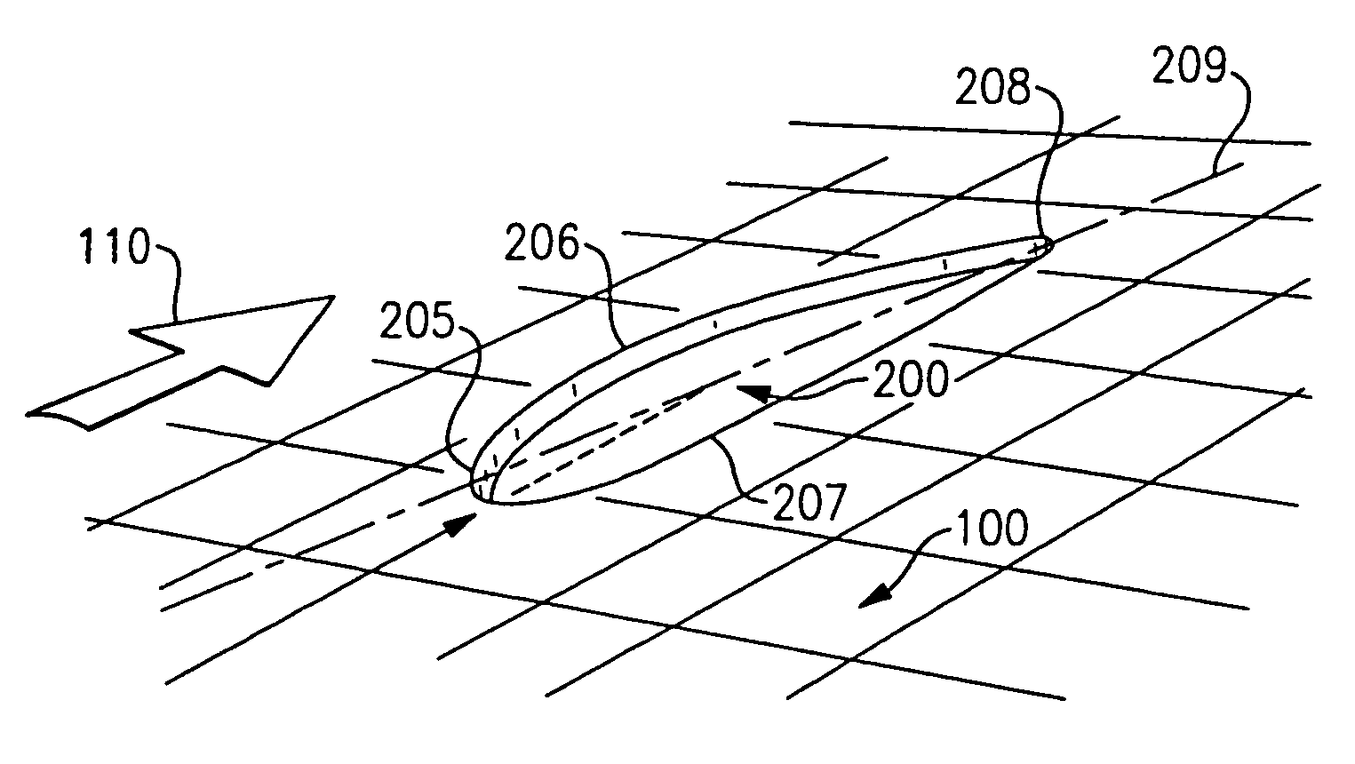
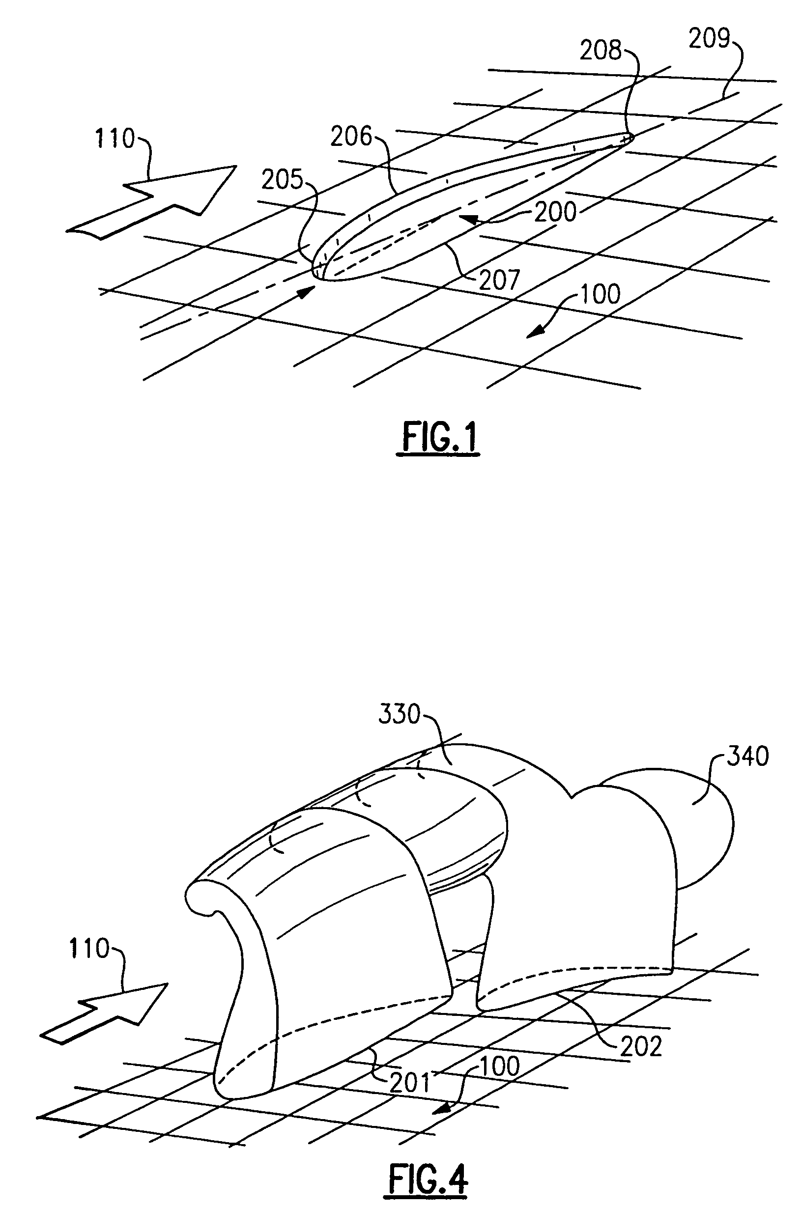
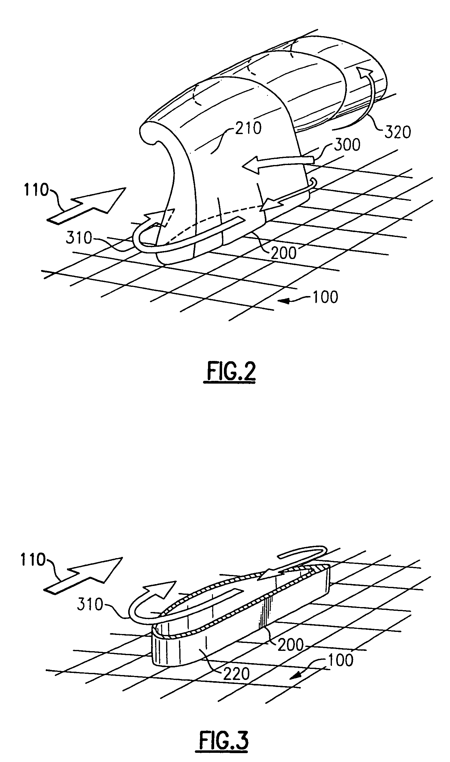
[0026]In the first embodiment of the invention as shown in FIGS. 1 and 2, a surface 100 separates an upper region containing a secondary fluid moving essentially parallel to said plate from a lower region having a primary fluid at higher pressure than the pressure of the secondary fluid. The surface 100 could be part of any device that mixes cross-streams of fluids, such as combustion chambers, bleed air discharge nozzles and thrust vectoring nozzles of gas turbine engines.

[0027]In a jet engine combustion chamber, the primary air is combustion-free air injected into a combustion chamber and is referred to as quench air and the secondary air is air having fully or partially burned fuel and is referred to as front-end air.

[0028]In a jet engine bleed air discharge nozzle, the primary air is compressor bleed air and the secondary air is air external to the compressor (e.g. fan-stream air). In a jet engine thrust vectoring nozzle, the primary air is compressed bleed air and the secondary...


PUM


Abstract

In an air mixing arrangement wherein a primary fluid is introduced through an opening in a wall to be mixed with a secondary fluid flowing along the wall surface, the opening is airfoil shaped with its leading edge being orientated at an attack angle with respect to the secondary fluid flow stream so as to thereby enhance the penetration and dispersion of the primary fluid stream into the secondary fluid stream. The airfoil shaped opening is selectively positioned such that its angle of attack provides the desired lift to optimize the mixing of the two streams for the particular application. In one embodiment, a collar is provided around the opening to prevent the secondary fluid from contacting the surface of the wall during certain conditions of operation. Multiple openings maybe used such as the combination of a larger airfoil shaped opening with a smaller airfoil shaped opened positioned downstream thereof, or a round shaped opening placed upstream of an airfoil shaped opening. Pairs of openings and associated collars maybe placed in symmetric relationship so as to promote mixing in particular applications, and nozzles maybe placed on the inner side of wall to enhance the flow characteristics of the primary fluid.

Description

BACKGROUND OF THE INVENTION [0001]The invention relates generally to the mixing of fluid flow streams and, more particularly to the injection of a primary fluid into a secondary fluid cross-stream, as found in, but not limited to, jet engine combustion chambers, jet engine bleed-air discharge nozzles, and jet-engine thrust vectoring nozzles.[0002]A fluid jet injected essentially normally to a fluid cross-stream is an important phenomenon that is ubiquitous in industrial processes involving mixing and dispersion of one fluid stream into another. For example, the “jet in cross-flow” phenomenon, as it is commonly called, dictates the efficiency of the mixing process between different gases in a jet combustor, controlling the rates of chemical reactions, NOx and soot formation, and unwanted temperature non-uniformity of gases impinging on the turbine blades.[0003]The jet-in-cross-flow phenomenon is also present at the discharge port of high temperature compressor bleed-air into the fan ...

Claims


Application Information

Patent Timeline
Patent Type & Authority Patents(United States)
IPC IPC(8): F23R3/06B67D7/74
CPCF01D5/145F02C6/08F02K1/28F02K1/46F23D14/583F02K1/38Y02T50/673Y10T137/0329Y02T50/60
Inventor BERTOLOTTI, FABIO P.LISCINSKY, DAVID S.SABATINO, DANIEL R.
Owner RTX CORP
Why Eureka
Try Eureka