Machine for transferring objects aligned in rows

a technology of objects and machines, applied in the field of transferring objects, can solve the problems of accelerating objects at a very large speed, unable to achieve affecting the speed of objects,

Inactive Publication Date: 2008-08-26
CERMEX OUEST CONDITIONNEMENT
View PDF17 Cites 22 Cited by
  • Summary
  • Abstract
  • Description
  • Claims
  • Application Information

AI Technical Summary

Benefits of technology

[0020]In practice, irrespective of the embodiment, it may be advantageous for the pushing members to be bars.

Problems solved by technology

The fact that, in this known machine, the first and second conveyors are perpendicular to one another constitutes a marked drawback due to the change of direction of movement of the objects, corresponding to the transfer from the first conveyor onto the second conveyor under the action of the pushing bar, which causes a canceling out of speed of the objects in the direction of movement of the first conveyor, immediately accompanied by a speeding up of the objects in the direction of the second conveyor.
If the pushing bar acted directly on the objects reaching it, the initial deceleration and the following acceleration would be very considerable, and the objects would be unbalanced and would fall over.
However, the machine thus equipped becomes complex and costly.
In addition, a change of trajectory of an angular amplitude of 90° may not suit all users.

Method used


Image

  • Machine for transferring objects aligned in rows
  • Machine for transferring objects aligned in rows
  • Machine for transferring objects aligned in rows

Examples


Embodiment Construction

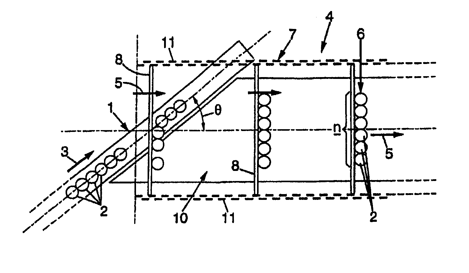
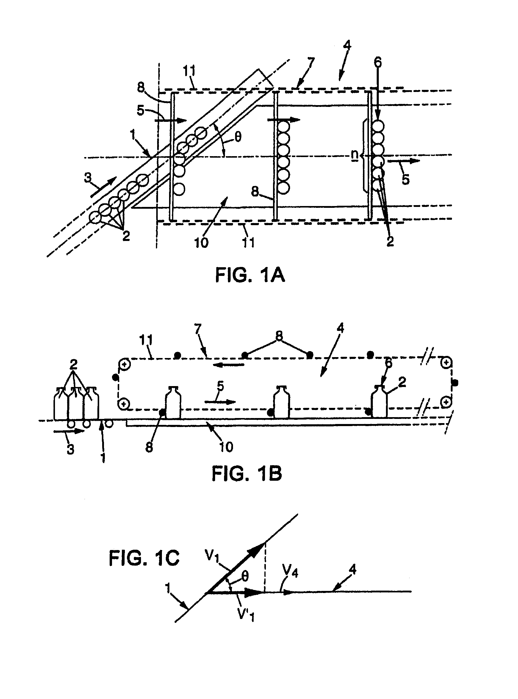
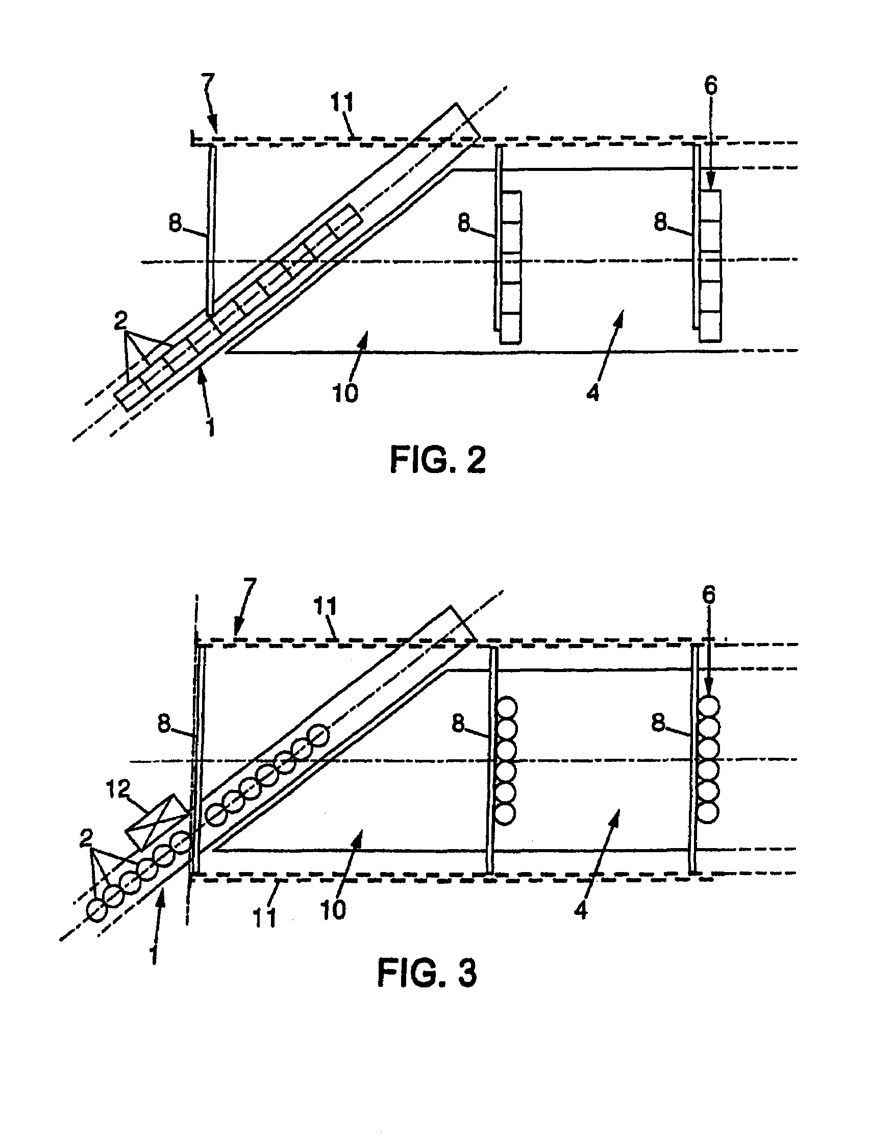
[0027]With reference first of all to FIGS. 1A and 1B, a first conveyor 1 (motor-driven conveyor, for example of the belt or tray conveyor type, or motorless conveyor) brings (arrow 3) objects 2 (for example bottles as illustrated) disposed in line one after the other; in the example illustrated, the objects 2 are juxtaposed to one another, although this disposition is not necessary as will appear hereinafter.

[0028]A second conveyor 4 clears (arrow 5) the objects 2 disposed in successive rows 6 of n objects abreast.

[0029]For this purpose, the second conveyor 4 comprises objects movement means 7 with at least one pushing member made up in the form of a pushing bar 8 which is movable (arrow 5) in order to be brought into lateral contact with n objects aligned on the first conveyor to push them, together, onto a tray 10 of the second conveyor where they are disposed in a row of n objects. The tray 10 extends laterally to the first conveyor 1 as appears in FIG. 1A.

[0030]The first and sec...


PUM


Abstract

A machine for transferring in successive rows objects initially aligned on a first conveyor. A second conveyor comprises a tray lateral to the first conveyor and a device for displacing objects with at least one push-member mobile transversely to the first conveyor such that it is urged into lateral contact with n objects on the first conveyor to push them back together in a row onto the tray along a direction forming an angle θ ranging between 0 and 90° exclusively relative to the first conveyor. Thus, the objects have speed components which are never null along the directions of movement the conveyors.

Description

BACKGROUND OF INVENTION[0001]The present invention relates to the field of transferring objects, and more specifically it relates to the transfer in successive rows of initially aligned objects.DESCRIPTION OF RELATED ART[0002]Document GB-A-2 174 667 describes a machine for transferring objects comprising:[0003]a first conveyor suitable for bringing the objects placed in line one after the other,[0004]a second conveyor extending perpendicularly to the first conveyor with its entrance end adjacent to the latter,[0005]and a pushing bar extending transversely to the direction of the second conveyor and movable parallel to the direction of the latter so that it comes into lateral contact with n objects on the first conveyor in order to push them together, in a row, onto the second conveyor.[0006]The fact that, in this known machine, the first and second conveyors are perpendicular to one another constitutes a marked drawback due to the change of direction of movement of the objects, corr...

Claims


Application Information

Patent Timeline
Patent Type & Authority Patents(United States)
IPC IPC(8): B65G25/00B65G47/22B65G47/71B65G47/84
CPCB65G47/715B65G47/841B65G2201/0244
Inventor GOSSET, FRANCOIS
Owner CERMEX OUEST CONDITIONNEMENT
Why Eureka
Try Eureka