Stow abort mechanism for a ram air turbine

a technology of air turbine and abort mechanism, which is applied in the direction of liquid fuel engines, vessel construction, marine propulsion, etc., can solve the problems of rigging, logic circuitry of stow panel, electrical harness and stow panel, and the logic circuitry of contact with the door is somewhat costly

Active Publication Date: 2008-08-26
HAMILTON SUNDSTRAND CORP
View PDF5 Cites 32 Cited by
  • Summary
  • Abstract
  • Description
  • Claims
  • Application Information

AI Technical Summary

Problems solved by technology

Misalignment of the blades can cause them to contact the door and damage can result.
The problem with this type of stow abort system is that the switch, rigging, electrical harness and stow panel logic circuitry are somewhat costly.

Method used


Image

  • Stow abort mechanism for a ram air turbine
  • Stow abort mechanism for a ram air turbine
  • Stow abort mechanism for a ram air turbine

Examples


Embodiment Construction

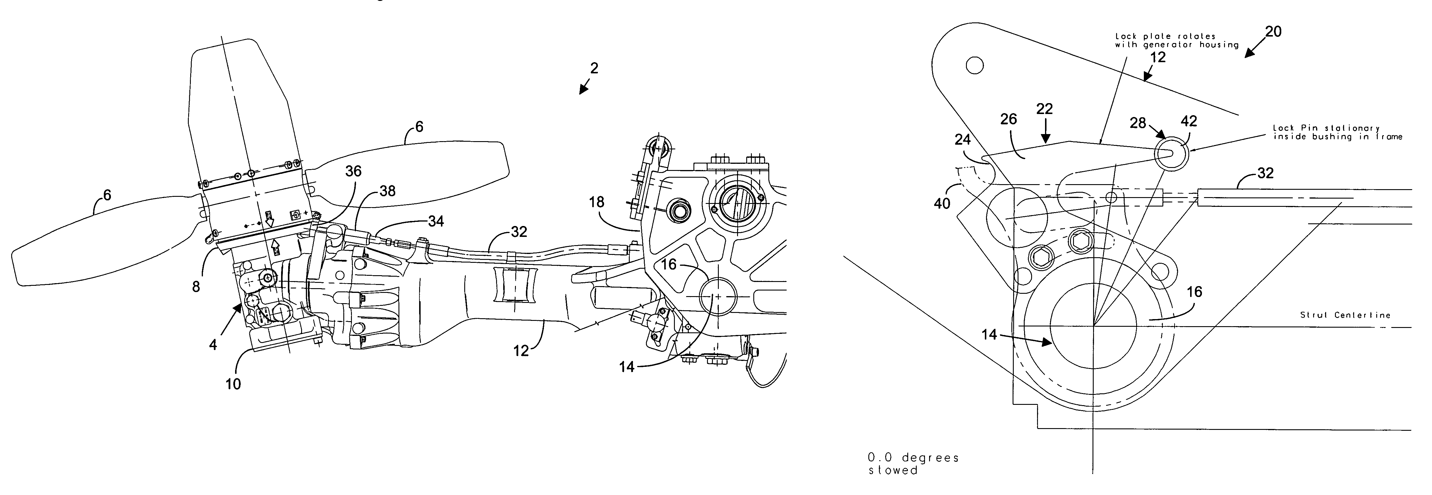
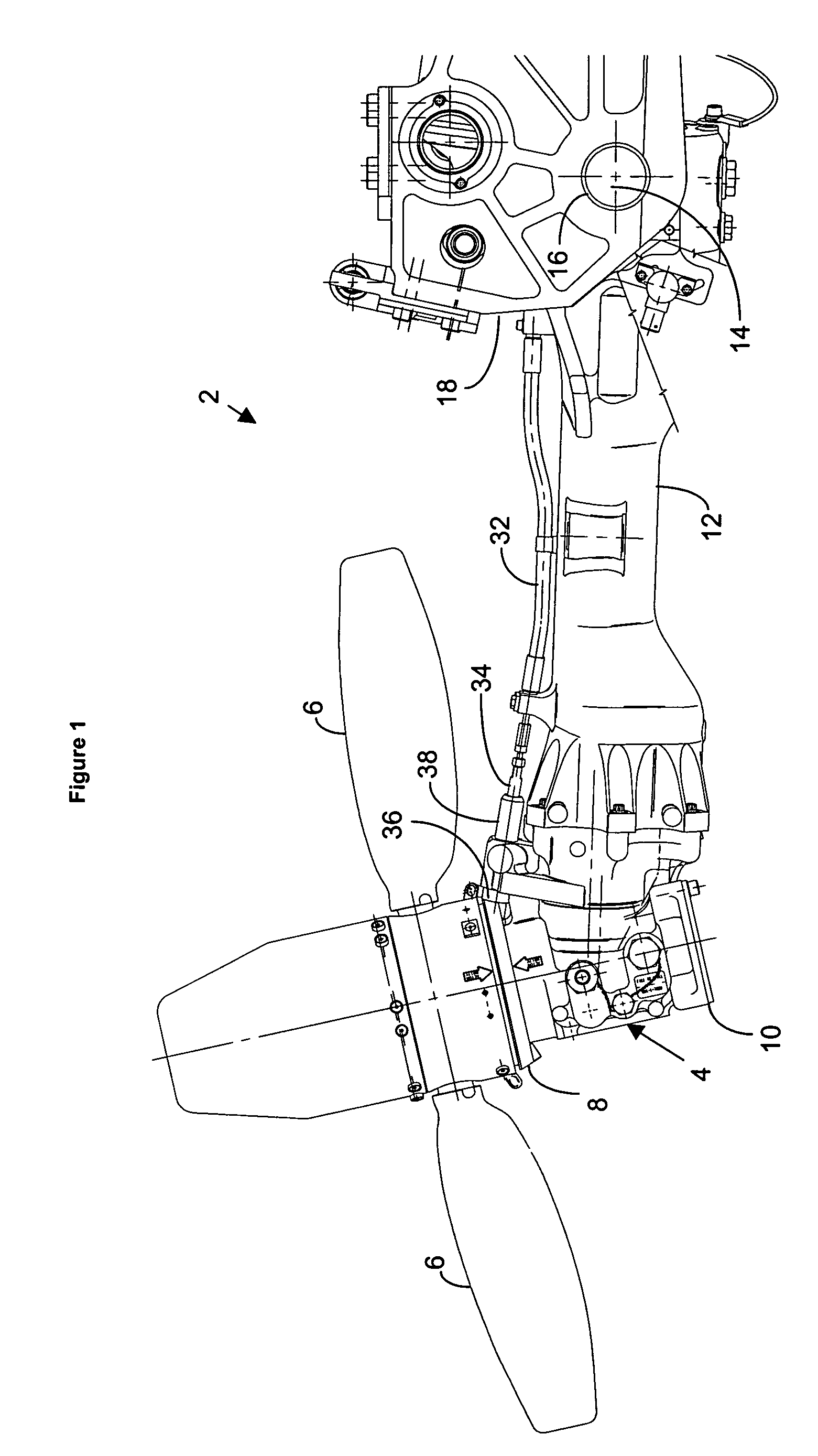
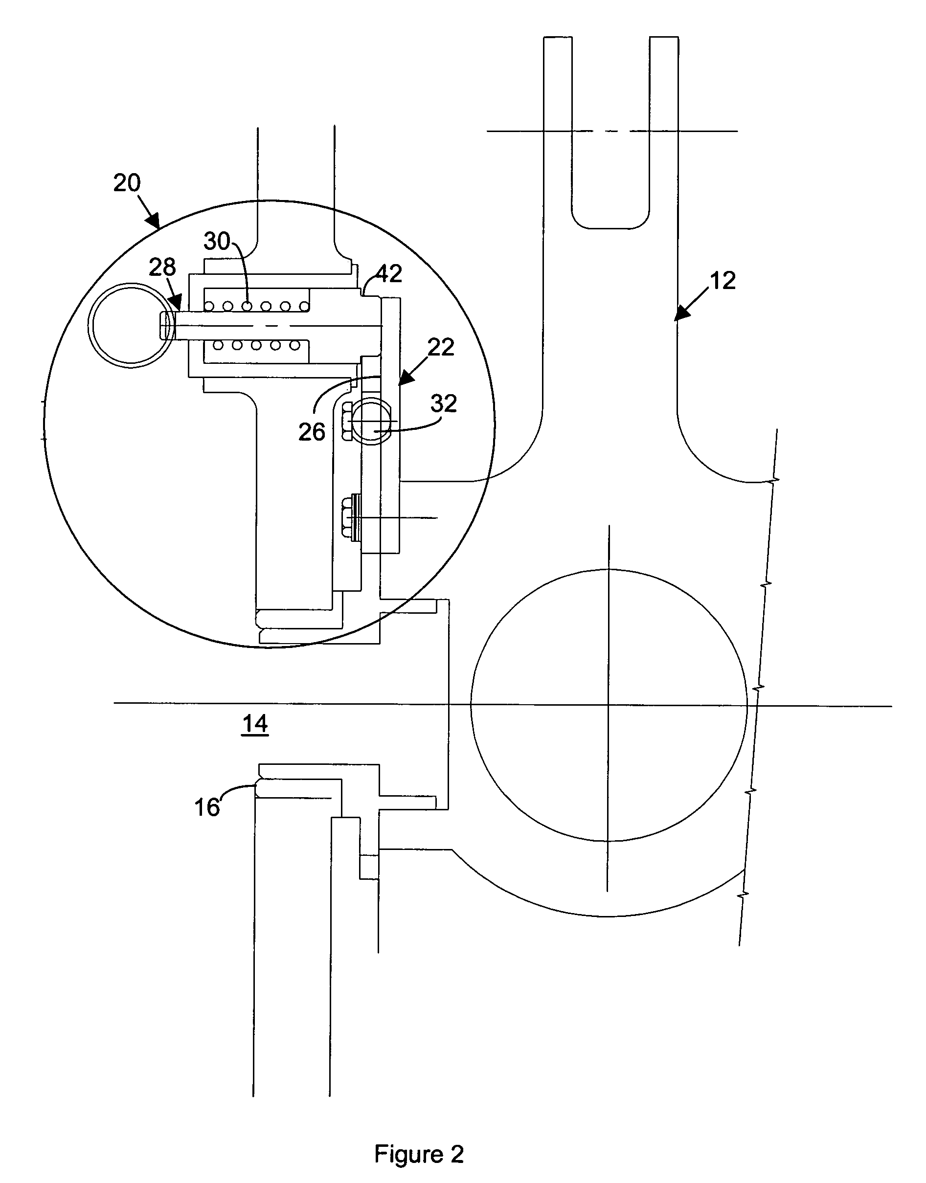
[0016]FIG. 1 is a cut-away side view of a RAT 2 according to one possible embodiment of the invention in a stowed position. The RAT 2 has a turbine 4 with turbine blades 6 that rotate about a turbine driveshaft 8 coupled to a lower gear box 10. The turbine 4 and lower gear box 10 mounts on a RAT strut 12 that rotates on a pivot post 14 within journal bearings 16, which are mounted in a RAT frame 18. FIG. 2 shows a cut-away end view of a possible embodiment of a stow abort mechanism 20 with the RAT 2. FIG. 3 shows a side view of the stow abort mechanism shown in FIG. 2 in a stowed position. The stow abort mechanism 20 comprises a lock plate 22 that rotates with the RAT strut 12. The lock plate 22 has an aperture 24 and a sliding surface 26. The aperture may comprise any convenient shape along the sliding surface 26, such as a hole, an indentation, or a slot along a side of the sliding surface 26 as shown. The stow abort mechanism 20 also comprises a stow abort lock pin 28 that contac...


PUM


Abstract

A stow abort mechanism for a ram air turbine (RAT) with a strut that rotates a turbine with associated blades from a stowed position to a deployment condition comprises a stow abort lock plate with an aperture that rotates with the strut and a stow abort lock pin that engages the aperture in the stow abort lock plate when the blades do not align properly for rotating the strut back into the stowed position.

Description

FIELD OF THE INVENTION[0001]The invention relates to emergency supplemental power supplies for aeronautical applications, and more particularly to an improved ram air turbine for generating emergency supplemental power for aircraft in flight.BACKGROUND OF THE INVENTION[0002]A ram air turbine (RAT) is a device for generating emergency supplemental power in a wide variety of aircraft. A RAT may generate hydraulic power, electric power or both. A RAT incorporates a turbine that extracts power from an air stream proximate the aircraft in flight. A typical RAT in current use is described in U.S. Pat. No. 4,743,163 to Markunas et al., owned by the assignee of this application, and incorporated herein by reference. The turbine is coupled to suitable power generating equipment, such as a hydraulic pump for hydraulic power and an electric generator for electric power, or both in the case of a hybrid RAT.[0003]The general operation of a RAT requires that it rotate from a stored position to a ...

Claims


Application Information

Patent Timeline
Patent Type & Authority Patents(United States)
IPC IPC(8): F03D11/04
CPCB64D41/007
Inventor RUSS, DAVID E.
Owner HAMILTON SUNDSTRAND CORP
Why Eureka
Try Eureka