Air-steam combined circulating device and air turbine circulating device

A combined cycle and steam technology, which is applied in the direction of steam engine equipment, combined combustion mitigation, mechanical equipment, etc., can solve the problems of low power generation efficiency, large loss, large heat loss in coal gasification and purification, etc.

Active Publication Date: 2015-09-09
李华玉
View PDF4 Cites 13 Cited by
  • Summary
  • Abstract
  • Description
  • Claims
  • Application Information

AI Technical Summary

Problems solved by technology

[0002] In traditional coal-fired thermal power generation devices, due to the influence of material pressure and temperature resistance, there is a large temperature difference between the circulating medium (circulating water and water vapor) and the gas. The larger the temperature difference, the resulting heat energy The greater the loss converted into mechanical energy, the lower the power generation efficiency
In order to improve the efficiency of converting thermal energy into mechanical energy, people have developed new technologies, such as IGCC integrated coal gasification combined cycle power generation technology that combines coal gasification technology and efficient combined cycle, pressurized fluidized bed coal-fired combined cycle, and the use of Supercritical, ultra-supercritical coal-fired power generation technologies, etc.; in the IGCC integrated coal gasification combined cycle, the heat loss of coal gasification and purification is too large, and the improvement of thermal efficiency is not ideal; even if the cost increase and safety performance are not considered, people find that these Technical measures failed to reduce the temperature difference between gas and circulating working fluid as much as possible

Method used


Image

  • Air-steam combined circulating device and air turbine circulating device
  • Air-steam combined circulating device and air turbine circulating device
  • Air-steam combined circulating device and air turbine circulating device

Examples


Embodiment Construction

[0040] The first thing to explain is that in the expression of the structure and process, it will not be repeated if it is not necessary; the obvious process will not be expressed. The present invention will be described in detail below in conjunction with the accompanying drawings and examples.

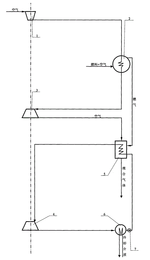
[0041] figure 1 The air-steam combined cycle plant shown is realized as follows:

[0042] (1) Structurally, it is mainly composed of a compressor, a boiler, a turbine, a second turbine, a waste heat boiler, a condenser and a circulating pump; the compressor 1 has an air channel to communicate with the outside, and the compressor 1 also has a compressed air channel and After the boiler 2 is connected, the boiler 2 has a compressed air channel to communicate with the turbine 3, the turbine 3 also has an air discharge channel to communicate with the waste heat boiler 5, the boiler 2 also has fuel and air supply channels to communicate with the outside, and the boiler 2 has a gas channe...


PUM


Abstract

The invention provides an air-steam combined circulating device and an air turbine circulating device, and belongs to the technical field of heat energy and power engineering. An air compressor, a boiler, a turbine, a second turbine, an afterheat boiler, a condenser, a circulating pump and a working machine are mainly used for forming the air-steam combined circulating device; the air compressor, the boiler and the turbine form an air power circulating system; the turbine provides power to the air compressor through mechanical connection; the second turbine, the afterheat boiler, the condenser and the circulating pump are formed to a steam power circulating system; and the turbine and the second turbine jointly provide the power to the working machine through mechanical connection. In this way, the air-steam combined circulating device is formed.

Description

Technical field: [0001] The invention belongs to the technical field of thermal energy and power engineering. Background technique: [0002] In traditional coal-fired thermal power generation devices, due to the influence of material pressure and temperature resistance, there is a large temperature difference between the circulating medium (circulating water and water vapor) and the gas. The larger the temperature difference, the resulting heat energy The greater the loss converted into mechanical energy, the lower the power generation efficiency. In order to improve the efficiency of converting thermal energy into mechanical energy, people have developed new technologies, such as IGCC integrated coal gasification combined cycle power generation technology that combines coal gasification technology and efficient combined cycle, pressurized fluidized bed coal-fired combined cycle, and the use of Supercritical, ultra-supercritical coal-fired power generation technologies, etc...

Claims


Application Information

Patent Timeline
Patent Type & Authority Applications(China)
IPC IPC(8): F01K23/08
CPCY02E20/16Y02E20/18
Inventor 李华玉
Owner 李华玉
Why Eureka
Try Eureka